


High-risk inspection is becoming increasingly difficult to justify with human entry. In mining sites, oil & gas refineries, disaster zones, and large industrial facilities, the constraint is the same: access is dangerous, conditions change quickly, and inspection coverage can’t keep pace.
That pressure is pushing operators toward remote inspection systems built around multiple coordinated platforms rather than a single tool. The goal is simple: more coverage with fewer people in the hazard zone.
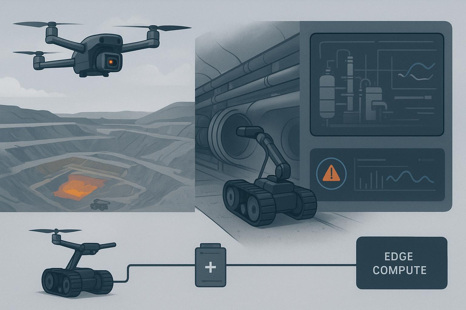
In practice, these systems combine UAVs for rapid aerial sensing, ground robots for close-range and confined inspections, and AI for anomaly detection and task prioritization. As they scale, one constraint becomes dominant: mission continuity is no longer defined by autonomy or sensing—it’s defined by the energy architecture behind the fleet. Multi-robot inspection rarely fails because the robots lack capability; it fails because energy, thermal behavior, and swap/charging logistics weren’t designed as a unified system.
This article outlines a practical, systems-level view of multi-robot inspection architecture, with a focus on how integrators can design energy continuity into UAV + UGV + AI workflows before field deployment exposes operational gaps.
Why high-risk inspection is moving toward multi-robot systems
From human entry to remote operations
A safer model isn’t simply “use robots.” It’s industrial remote operations: fewer people in the hazard zone, more sensing from standoff distance, and better triage so humans only enter when the risk is understood and justified.
The safety logic is well established. The National Safety Council highlights remote-controlled robots as high-value tools for reducing exposure in tasks like confined entry inspections and working at height (see the NSC white paper “Improving Workplace Safety with Robotics”).
Why single-tool solutions are no longer sufficient
High-risk sites break single-tool approaches because the environment is heterogeneous:
open areas + tight corridors + vertical structures
multiple sensing modalities (thermal + RGB + gas + LiDAR + acoustic)
time windows that don’t wait (shutdown windows, weather windows, incident response)
A drone can screen quickly but can’t do persistent close-up work in every space. A ground robot can get close but can’t provide rapid global context. AI can prioritize, but it can’t create ground truth without sensors.
Operational constraints in hazardous environments
Across the environments you care about, the constraint pattern repeats:
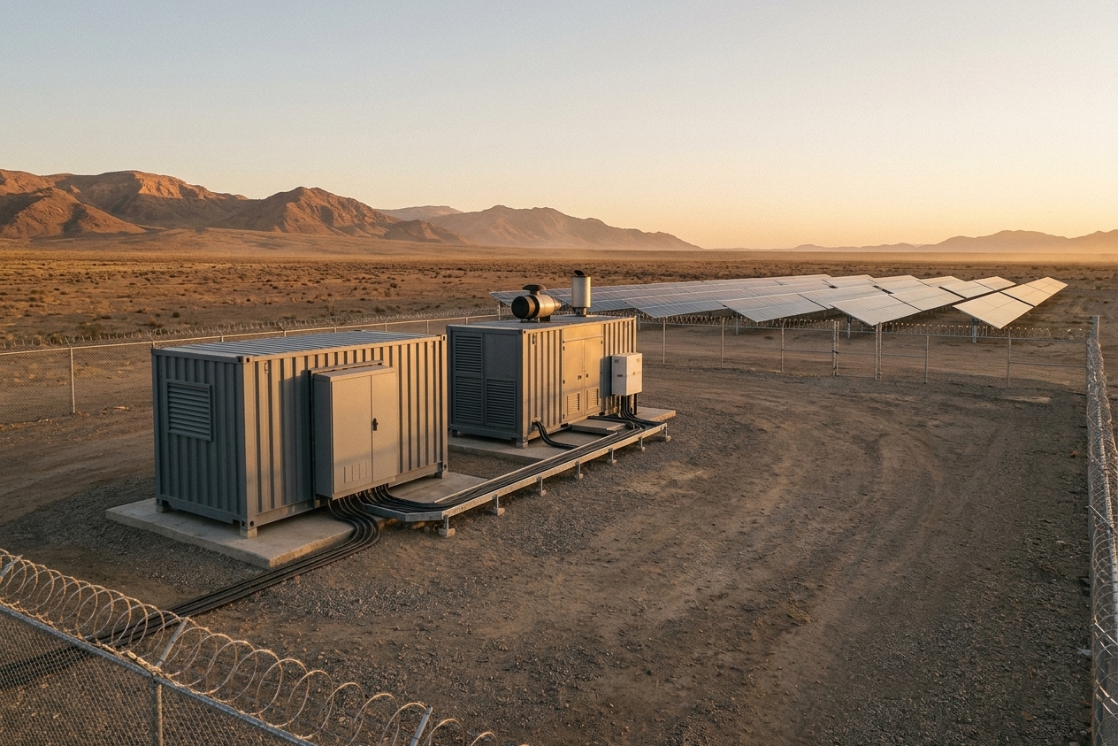
Industrial sites: dust, vibration, long routes, dense equipment, and mixed human/robot traffic
Refineries and process plants: heat, corrosion, tight access around pipe racks, and hazardous-area constraints
Remote and disaster environments: unstable structures, degraded comms, weather exposure, and long time-to-repair
These constraints are why heterogeneous fleets outperform “one platform everywhere.”
The role split: UAVs, ground robots, and AI in modern inspection workflows
The role split matters because each layer runs a different duty cycle—and duty cycles are what drive energy sizing, swap strategy, and uptime planning at fleet scale.
This is the practical UAV UGV inspection workflow most integrators converge on.
UAVs as fast-area mapping and aerial detection tools
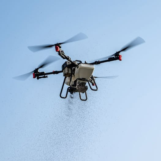
UAVs are the scout layer:
rapid mapping and overview capture
thermal scanning to surface hotspots
high-angle access to elevated assets
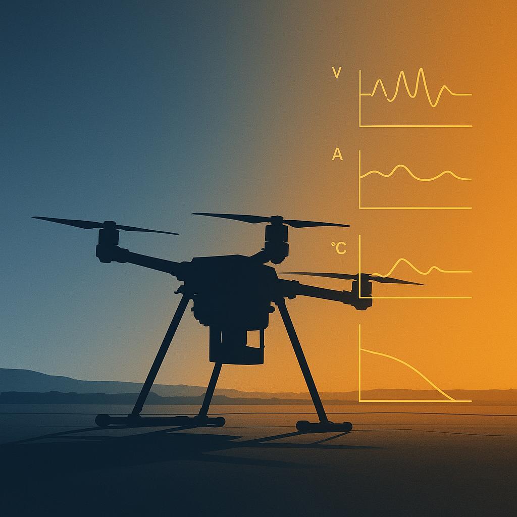
Their limitation isn’t intelligence. It’s power: flight is energy-expensive, and endurance collapses under payload, wind, and hover time.
Ground robots for confined or contact-level inspection
Ground robots earn their place when the mission needs:
repeatable close-range inspection
confined-space access without human entry
contact-level sensors (e.g., ultrasonic thickness, acoustic)
They also bring their own constraints: rough terrain and sealed enclosures can drive unpredictable thermal behavior.
AI as the decision layer: detection, prioritization, and re-tasking
AI’s real value is throughput: it detects anomalies in high-volume sensor streams, prioritizes follow-up, and reduces the human review burden.
But AI isn’t free. More inference time and more sensor duty cycle add power draw and add heat—especially when the platform is sealed for ingress protection.
AI improves decision efficiency, but it indirectly increases system energy demand rather than reducing it.
Where system performance actually fails: energy, endurance, and mission continuity
This is where most programs lose uptime: not in sensing or autonomy demos, but in repeatable, shift-by-shift energy availability and the operating processes around it.
Multi-robot inspection doesn’t usually break at perception. It breaks at operations.
A useful field framing is that robots tend to run out of energy long before they run out of work, which constrains persistent missions (see IEN’s “Robots Run Out of Energy Long Before They Run Out of Work to Do”).
Why energy supply becomes a system bottleneck in multi-robot operations
In a single-platform demo, energy is a spec.
In fleet deployment, energy is an operations dependency.
Multi-robot systems don’t fail at the device level—they fail at the fleet energy coordination level.
Fleet operations create failure modes that don’t show up in lab tests:
charge-cycle pressure (higher cycles per calendar month)
swap logistics dependency (availability depends on spares + people + process)
thermal accumulation (short turnarounds stack heat)
voltage sag under load as packs age or temperature shifts
A research thread on long-horizon multi-robot systems explicitly frames battery capacity, recharge logistics, and compute budgets as scaling bottlenecks.
UAV battery limitations under continuous deployment cycles
UAV duty cycles tend to be short, repetitive, and peak-load heavy:
takeoff and climb spike current
hover and gust correction sustain current
comms and payloads add both mass and power draw
In continuous operations, you’re optimizing not just flight time, but turnaround time. That’s where heating, recharge limits, and voltage stability become mission-level constraints.
Ground robot power demand vs runtime expectations
UGVs are often assigned the “slow, close, and persistent” tasks.
That makes energy consumption less spiky than UAVs, but not necessarily lower. Long routes, stop-start inspection patterns, heavy sensors, and autonomy compute in GNSS-denied spaces can compress usable runtime—and heat build-up can force derating.
Why AI becomes an energy multiplier
AI raises compute duty cycle, sensor duty cycle, and data handling time. Treated as a bolt-on, it compounds thermal rise and derating across repeated cycles—shrinking usable capacity faster than most teams expect.
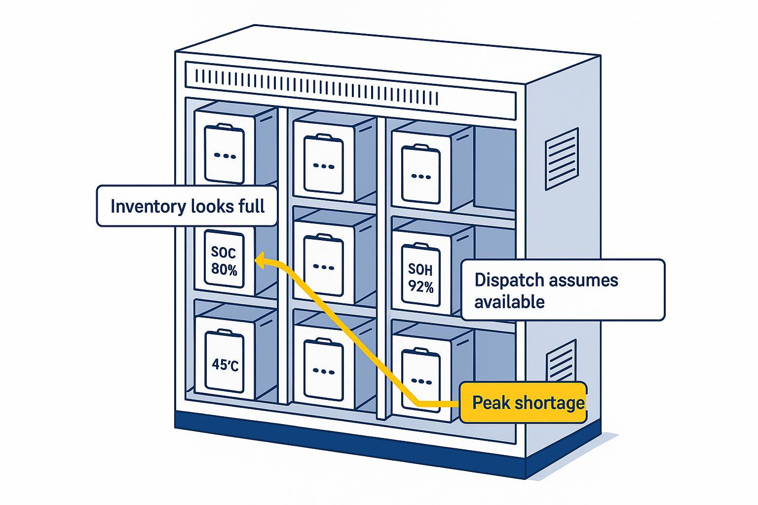
Why energy architecture decides multi-robot reliability
If you’re integrating UAVs, UGVs, and AI into one inspection workflow, you can’t treat batteries as interchangeable “consumables.” At fleet scale, energy architecture becomes part of the autonomy stack: it shapes what missions are feasible, how safely platforms can operate near the edge of their envelopes, and how predictable your coverage is from shift to shift.
In practice, that means specifying (and validating) energy behavior the same way you specify sensing and navigation: voltage stability under worst-case segments, thermal limits under turnaround cycles, and fleet-visible telemetry (SOC/SOH/temperature) that supports scheduling and retasking decisions.
Battery requirements for multi-robot inspection ecosystems
Use this section as a checklist for specifying the energy layer the same way you specify perception and navigation: clear requirements, clear validation, and clear fleet-level data.
Voltage architecture and system stability under field conditions
Requirement | Why it matters | What to validate |
|---|---|---|
Voltage stability under load | Prevents resets, cutoffs, and unpredictable end-of-mission behavior | Worst-case current segments, cold/hot starts, aged-pack profiles |
Thermal behavior over duty cycles | Heat stacking drives derating and accelerates aging | Turnaround cycles, enclosure heat soak, charge acceptance limits |
Fleet-level consistency | One weak pack sets the uptime ceiling | Variance across packs, IR growth trends, screening rules |
Usable telemetry | Scheduling needs SOC/SOH/temp you can trust | Data accuracy, update rates, interface compatibility |
A common industrial UAV range is 12S–18S. The critical question isn’t the cell count—it’s whether the system maintains minimum voltage under your worst-case segment.
If you need a focused engineering view on sag behavior and why it predicts mission stability better than headline ratings, a practical reference is drone battery voltage sag and fleet reliability.
Cycle consistency across fleet-level operations
Fleet uptime depends on the worst pack that still gets deployed.
So cycle consistency matters as much as cycle life:
predictable internal resistance growth
predictable voltage response under repeat loads
predictable end-of-mission behavior across packs
Variance forces you to inflate reserves, which reduces coverage per shift.
Temperature and environmental derating in real deployments
Derating is where paper specs fail.
If you operate in hot mines, refinery pipe racks, wet disaster zones, and exposed remote corridors, you need to define temperature derating explicitly: usable power and capacity versus temperature, plus operational constraints (preheat, cooldown, max turnaround).
For context on inspection and mapping conditions and adaptation factors, a useful starting point is lithium batteries for mapping and inspection drones (environmental adaptation).
Why C-rate is not enough without system-level validation
C-rate is a label, not a validation method.
You need explicit checks for:
continuous vs burst discharge capability
voltage sag under load in your worst-case segments
thermal rise under duty cycle (not a single pull)
protection behavior and recovery
Telemetry matters here. If you’re integrating energy data into mission scheduling, a useful overview is UAV battery communication protocols and BMS-flight controller integration, which clarifies what data (SOC/SOH/temperature) actually supports fleet decisions.
Operational reality: reliability, swapping strategy, and fleet uptime
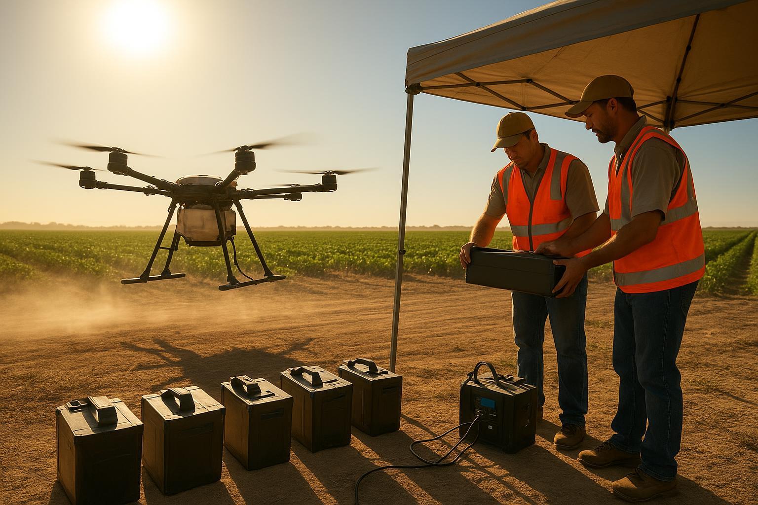
Battery swap cycles and mission continuity design
Swapping improves uptime only if the swap system is engineered. Otherwise you move failure from “endurance” to “process variance.”
Design questions:
How many spares per active platform are required for the mission window?
What is the swap time and error rate in PPE, heat, rain, or darkness?
What is the rule for packs that show abnormal sag or temperature rise?
If the SOP allows “any available pack,” you are engineering in variance. Variance is the enemy of predictability.
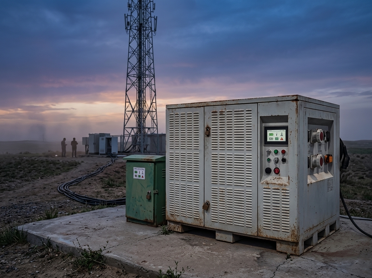
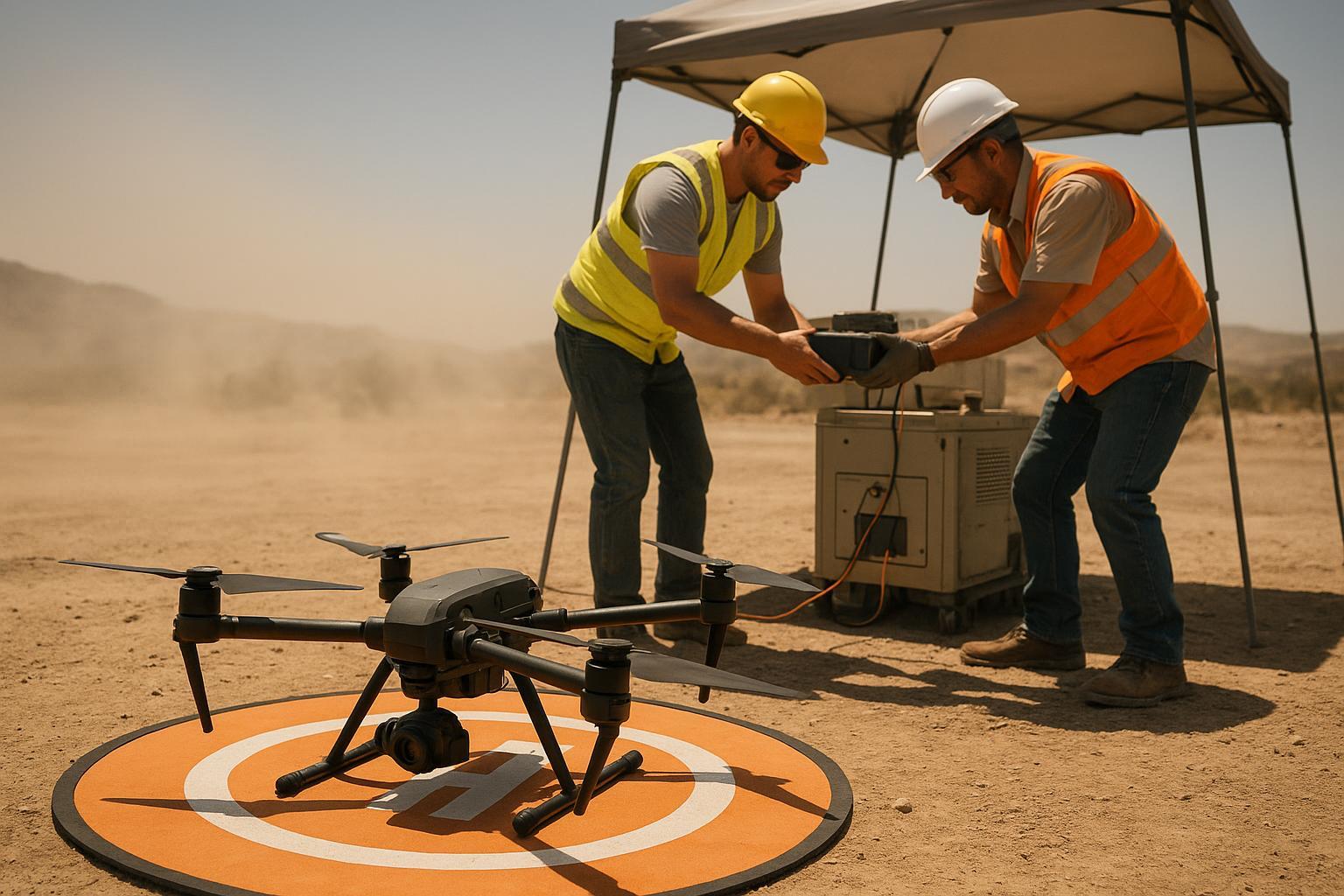
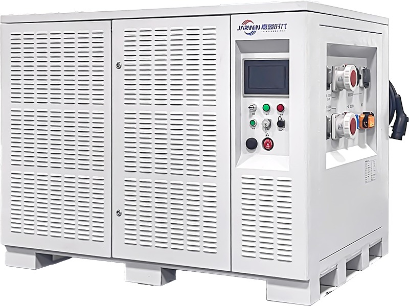
Charging logistics in remote or harsh environments
Charging is often the true bottleneck.
Field deployments face misalignment, contamination, and environmental stressors that don’t exist in clean labs.
Failure modes: voltage sag, imbalance, thermal drift
The most expensive failures are the ones that look like “random glitches.” In practice, they’re often power-system effects.
sag-induced resets / undervoltage cutoffs
imbalance reducing usable capacity
thermal drift reducing recharge acceptance and accelerating aging
Treat these as fleet health signals, not one-off incidents.
Integration challenges in multi-system inspection deployments
Interoperability between UAV, UGV, and AI systems
Multi-robot stacks fail at the seams:
inconsistent timestamps and map frames
mismatched mission state definitions
different comms assumptions (UAV has link; UGV is behind steel)
The practical fix is usually a strict internal interface contract: what telemetry is required, at what rate, and what safe-state behavior is required under degraded comms.
Power system compatibility constraints
Power compatibility is a hidden integration cost:
different voltage buses across platforms
connector and mechanical differences
BMS data interfaces (or none)
The operational consequence is inventory complexity: more SKUs, more troubleshooting variance, more training burden.
Next steps: spec the energy layer like it’s part of autonomy
If you’re building or scaling a multi-robot inspection program, treat the battery system as the constraint layer and validate it accordingly:
Define worst-case segments (peak current + temperature + duty cycle)
Specify continuous vs burst discharge requirements explicitly
Validate voltage sag under load with representative profiles
Engineer a battery swap strategy that controls variance (spares, screening rules, audit trail)
Require fleet-visible telemetry (SOC/SOH/temp) for scheduling decisions
When inspection uptime depends on continuous energy availability, battery architecture becomes a system design decision—not a procurement item.
If you want to make the energy layer predictable at fleet scale—by defining worst-case segments, validation profiles, swap/charge workflows, and telemetry requirements—you can discuss an engineering plan with Ini dia..