


A UAV battery is only as “smart” as the link that turns chemistry into actionable telemetry. In industrial flight conditions—vibration, EMI, temperature swings, and high transient current—your UAV battery communication protocol determines whether voltage, temperature, and SOC data arrives on time, stays intact, and carries validity signals the flight controller can trust.
This is a consideration-stage guide for integration teams planning flight controller battery integration end-to-end: protocol selection, telemetry fields, and the engineering workflow that avoids surprises during bring-up.
Why UAV Battery Communication Matters in Real Flight Conditions
Battery telemetry is used in at least three places that affect real outcomes:
Flight safety logic (failsafes, return-to-launch thresholds, power limiting)
Energy planning (time-to-empty, reserve margins, mission planning)
Maintenance decisions (pack retirement, balancing issues, connector degradation)
The practical question is not “can we read battery data?” It’s whether the UAV battery communication protocol and validation logic stay reliable when motors, ESCs, and payload electronics are generating noise.
What Happens When Battery Communication Fails
When communication fails, the immediate technical problem is “missing data.” The operational problem is worse: the aircraft continues making decisions with an incorrect model of available power.
A typical failure chain looks like this:
Telemetry interruption → voltage / temperature / current become stale or invisible
Controller decisions degrade → incorrect reserve estimate, missed thermal derating, wrong low-voltage thresholds
Outcome risk increases → unexpected power loss, over-discharge, or thermal events
Warning: A battery can be electrically “alive” while being information-dead. If the flight controller can’t trust the data, it can’t reliably enforce safe limits.
How Battery Data Improves Flight Efficiency and Maintenance
Two metrics drive most “smart battery” value for fleets:
State of Charge (SOC): Helps mission logic decide whether to continue, shorten, or abort a route—especially when conditions shift (wind, payload changes, climb segments).
State of Health (SOH): Enables predictive maintenance by identifying packs whose internal resistance, capacity fade, or imbalance behavior is trending toward failure.
In practice:
SOC informs route planning and return-to-launch (RTL) decisions.
SOH informs retirement thresholds (many teams use “<80%” as an initial heuristic, but the correct threshold should be tied to mission reserve policy and risk tolerance).
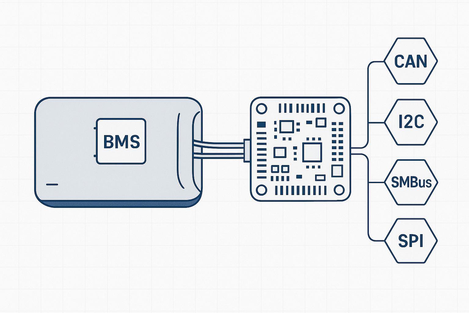
Choosing a UAV Battery Communication Protocol: I2C vs CAN Bus vs SMBus vs SPI
There isn’t a universally “best” UAV battery communication protocol. There is only “best under your constraints,” which are usually:
EMI/noise environment and harness length
Node count (battery, power module, ESCs, sensors)
Data freshness requirements and failure handling
Integration complexity (tooling, firmware, diagnostics)
Teams also sanity-check the ballpark throughput they need. Commonly quoted reference points (always verify against your exact silicon, bus configuration, and stack overhead) include:
I2C: often discussed from 100 kHz (standard mode) up to 3.4 MHz (high-speed mode)
Classic CAN: commonly quoted up to 1 Mbps on many UAV implementations
SPI: often in the tens of MHz (sometimes higher), typically for short, controlled runs
Quick comparison (engineering-first)
Protocol | Typical fit in UAVs | Strengths | Common risks | When it’s a strong choice |
|---|---|---|---|---|
I2C | Short-distance internal comms | Simple wiring, low cost | Noise sensitivity, distance limits | Inside a pack or tightly coupled modules |
CAN (incl. DroneCAN/UAVCAN) | Vehicle-level network | EMI robustness, multi-node, mature diagnostics | Topology/termination errors; bus saturation | Industrial UAVs, longer harnesses, many peripherals |
SMBus | Smart battery ecosystems | Standardized smart-battery command/data model | Stack/tooling mismatch; gateway complexity | Packs designed as smart batteries with standardized reporting |
SPI | High-speed local link | High throughput, deterministic | More wires; short distance | Data-intensive local modules, not long harnesses |
I2C: Simple and Cost-Effective for Low-Speed Systems
I2C’s appeal is straightforward: two wires, low cost, simple devices. In UAV battery systems, it often appears as an internal interface—inside a smart battery, between gauges, sensors, and the BMS MCU.
Where it can go wrong is when teams stretch I2C beyond what it tolerates:
Longer harnesses exposed to motor/ESC noise
Poor grounding/return paths
Weak error handling (data becomes “wrong” instead of “missing”)
Use I2C where the physical environment is controlled and the distance is short.
CAN Bus: Reliable Communication for Industrial UAVs
If you’re making a serious CAN bus vs I2C for UAV decision, treat it as a reliability decision first and a cost decision second.
CAN is commonly chosen when you need robust communication in noisy environments and want multiple nodes on one bus. In UAV ecosystems, CAN often shows up with higher-level protocols like DroneCAN/UAVCAN.
PX4’s official guidance frames DroneCAN as an open CAN-based protocol for flight controllers and peripherals, and it supports battery monitoring by subscribing to battery messages (for example, enabling the battery subscription parameter UAVCAN_SUB_BAT). See PX4’s DroneCAN documentation.
Key reasons CAN is favored in industrial integration:
Differential signaling and error handling properties suited to EMI-heavy environments
Multi-node support (battery monitor, power module, ESCs, sensors)
A better fit for larger airframes and longer wiring runs
Key engineering reality:
CAN is reliable when the bus is engineered correctly: termination, topology discipline, connector quality, and traffic management matter.
SMBus: Optimized for Smart Battery Management
SMBus is closely related to I2C, but designed around system management (standard commands, expected behaviors, and typical usage in smart-battery ecosystems).
In UAV integration, SMBus becomes attractive when:
You’re working with a SMBus smart battery that already exposes standardized reporting
Your downstream stack expects that data model and you want a predictable semantic contract
The trade-off is architectural: if your flight controller and vehicle network are already CAN-centric, SMBus can push complexity into gateways and firmware glue.
SPI: High-Speed Interface for Data-Intensive Systems
SPI is the “high-speed local link” option. It’s fast and deterministic, but it’s usually best kept inside a controlled enclosure rather than across the airframe.
SPI tends to be chosen when:
Data volume is high
Latency budget is tight
Wiring length is short and controlled
Its downside for battery-to-flight-controller links is practical: more wires and tighter constraints on harness design over distance.
How to Select the Right Protocol for Your UAV System
A pragmatic selection approach is to start from the failure modes you can’t tolerate and decide which UAV battery communication protocol reduces exposure.
High-EMI environment / longer harness / many nodes → prioritize CAN
Cost-sensitive, short-distance internal comms → I2C
Standardized smart-battery semantics + management commands → SMBus
High data rate, short distance, local module integration → SPI
Battery Data That Drives Flight Decisions
Battery telemetry is only useful if it is:
Accurate (calibration and estimation logic)
Fresh (update rate and latency)
Trusted (error detection and fail-safe behavior)
This is why “protocol choice” and “data choice” are inseparable: your UAV battery communication protocol determines how easily you can detect staleness, corruption, and partial failure.
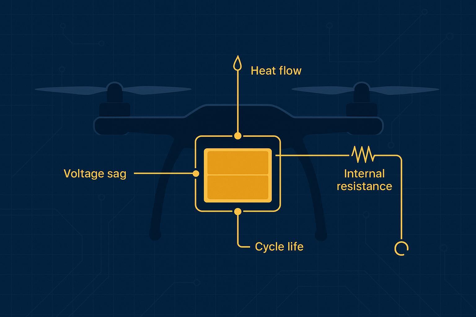
Core Parameters: Voltage, Current, and Temperature
These are the baseline signals for any battery integration:
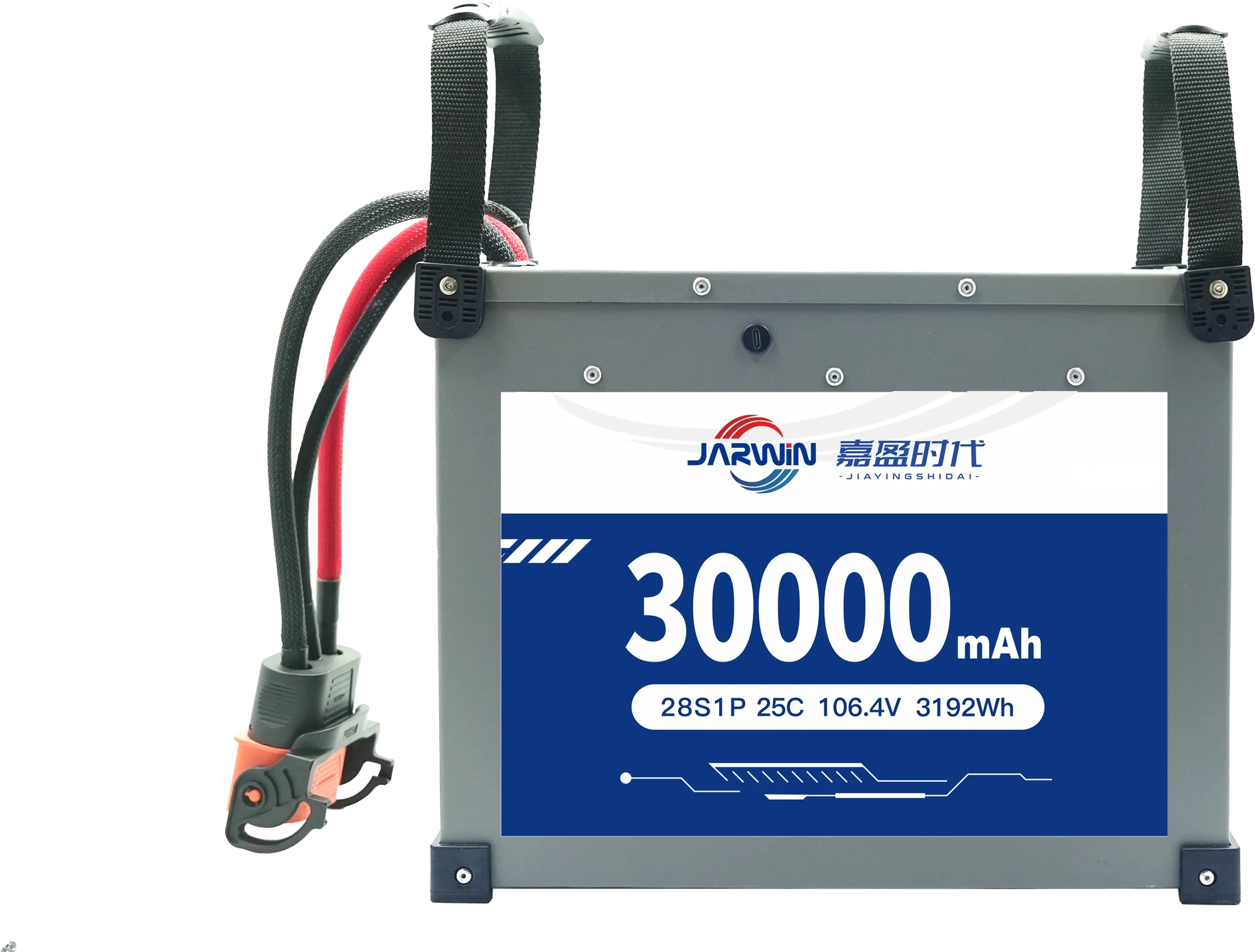
Voltage (V) → indicates available output capability and sag under load. As a rough reference, many Li-ion chemistries are commonly discussed around ~3.6–3.7 V nominal per cell; the pack voltage is the series sum and must be mapped to your specific chemistry, C-rate, and low-voltage policy.
Current (A) → reveals load dynamics and helps detect abnormal draw. Under heavy payload or aggressive maneuvers, current spikes can be the earliest indicator that reserve margins are collapsing.
Temperature (°C) → defines safety boundaries; informs derating and shutdown thresholds. Extremes on either side matter: high temperature increases safety risk and accelerates aging; low temperature reduces available capacity and output capability.
From a controller perspective, you want both instantaneous values and trends (temperature slope, sag magnitude under a known throttle segment).
Advanced Metrics: SOC and SOH
SOC and SOH are where integration projects often fail—not because teams don’t expose the fields, but because estimator behavior under real flight dynamics is not validated.
State of Charge (SOC, %): A percentage estimate of remaining energy. It must remain stable under aggressive current swings; otherwise RTL triggers and reserve margins become unreliable.
State of Health (SOH, %): A percentage indicator of degradation (capacity fade, internal resistance increase, imbalance behavior). Many teams use ~80% SOH as an initial maintenance/retirement heuristic, but the right threshold should be tied to mission reserve policy, environmental conditions, and risk tolerance.
This is also where BMS telemetry for drones should include explicit validity/quality signals (e.g., “SOC valid,” “SOH learning state,” “temperature sensor fault”) so the flight controller can decide what to trust.
If you want supplier-side context on how smart BMS monitoring is positioned in drone applications, some battery OEM/ODM vendors publish high-level overviews of UAV battery solutions and customization—treat these as product context, not protocol specifications.
How Battery Data Directly Impacts Flight Safety
A clean mapping is:
Temperature → thermal derating logic to reduce risk of thermal runaway
SOC → prevents over-discharge and supports reserve-aware RTL decisions
SOH → early warning for packs whose behavior is drifting toward failure
The key is to define “what the controller does when data is missing or inconsistent.” Which leads to integration architecture.
Battery–Flight Controller Integration: Workflow, Architecture, and Challenges
Integration isn’t just wiring. It’s the design of a decision loop:
Battery measures and estimates
BMS formats data
Flight controller ingests data
Controller uses it for limits, failsafes, logging, and maintenance actions
Typical Communication Workflow Between Battery and Flight Controller
A robust workflow typically includes:
Initialization → physical link up, node discovery (if applicable), and basic configuration checks (ID, cell count, nominal voltage)
Self-test → detect sensor faults, impossible values, and estimator readiness (for example, whether SOC/SOH is learned or still initializing)
Data synchronization → set the update rate, timestamps/sequence counters, and explicit validity flags
Then the steady-state cycle:
Periodic update → subscribe (CAN/DroneCAN-style) or poll (I2C/SMBus-style), depending on protocol and stack
Data return → voltage/current/temperature/SOC/SOH plus alarms and fault bits
Validation → CRC/checks (where available), range checks, and staleness timeouts using timestamps or sequence counters
Recovery → retry request, request a re-send, or re-initialize the link (the exact mechanism is stack-dependent)
Control adjustment → warnings, derating, RTL triggers, or landing logic
A simple in-flight control example (what “closed-loop” looks like in practice):
Voltage droops + SOC trending down → the controller can reduce peak power demand (limits/derating), warn the operator, and if thresholds are crossed, initiate RTL or a managed landing.
Temperature crosses a limit → the controller can cap thrust, reduce climb rate, or trigger a forced landing sequence—but only if the temperature field is fresh and marked valid.
If your ecosystem is CAN-centric, DroneCAN battery monitoring is typically implemented as a subscription model rather than a “poll-and-hope” pattern, which can reduce integration ambiguity and improve logging traceability.
Vendor-Specific Integration Approaches
These examples set expectations for what “integration” can mean in practice:
DJI (as an example): Many closed ecosystems use proprietary protocols with tight hardware/firmware coupling. The upside is a highly integrated experience. The trade-off is reduced transparency and portability for third-party integration.
Freefly Systems (as an example): Some industrial-focused stacks lean toward CAN-based approaches because they scale to multi-node telemetry and diagnostics.
The takeaway is not “copy a vendor,” but: decide whether your architecture needs proprietary tight coupling (and accepts lock-in) or standardized interfaces (and accepts integration responsibility).
Key Engineering Challenges and Solutions
Challenge 1: EMI and noisy power environments
Risk: corrupted data, intermittent dropouts, false alarms
Mitigations: shielding, twisted pairs where appropriate, disciplined grounding/return paths, connector selection, and choosing an interface better suited for noisy environments (often CAN). At the harness/system level, also consider filtering, isolation (where appropriate), and strict topology/termination discipline.
Challenge 2: Latency and stale telemetry
Risk: controller acts on old SOC/temperature, creating wrong safety decisions
Mitigations: reduce payload to essential fields; increase update frequency where needed; implement staleness timeouts; ensure logging confirms freshness (timestamps/sequence counters help).
Challenge 3: Reliability and fault tolerance
Risk: single-point communication failures become safety failures
Mitigations: redundancy where appropriate (secondary measurement path, conservative fallback limits), validity flags, and graceful degradation.
A practical pattern is to define a minimum safe telemetry set and a clear trigger for “conservative mode”:
Minimum safe telemetry set: pack voltage + at least one temperature channel (and current if available)
Conservative mode trigger: SOC/SOH invalid, missing for N update intervals, or fails validation/staleness checks
Conservative mode behavior: fall back to voltage-based thresholds, tighten reserve margins, cap peak power, and prefer RTL/land decisions earlier
Use robust integrity checks (CRC where supported, counters, range checks) and define recovery behavior: on some stacks you can request re-send/retry at the application layer; regardless, the controller should treat missing/invalid data as a first-class state and switch to a conservative mode.
Where safety requirements are higher, teams also implement multi-link redundancy (primary + backup path) with explicit fault detection and failover criteria, so a comms fault degrades capability rather than creating an immediate safety hazard.
ArduPilot’s documentation shows how DroneCAN peripherals can feed structured telemetry into logs (for ESCs, CESC logs include voltage/current/temperature/RPM/error counts), supporting the operational value of CAN telemetry beyond “just wiring.” See ArduPilot’s DroneCAN ESC telemetry notes.
Common Integration Pitfalls Engineers Should Avoid
These are recurring failure patterns seen in UAV integration projects:
Protocol selection mismatch: choosing an interface that doesn’t tolerate the physical environment (noise + harness length) or the node count.
SOC accuracy not validated: SOC looks fine on the bench but drifts under dynamic load; RTL logic becomes unreliable.
Excessive communication delay: telemetry is “present” but stale; alarms arrive too late.
No redundancy or fallback logic: missing data becomes a hard failure instead of a controlled degradation mode.
Define your baseline telemetry set (often voltage + temperature + conservative current limits) and design a fallback mode the flight controller can enforce even when smart metrics (SOC/SOH) are invalid.
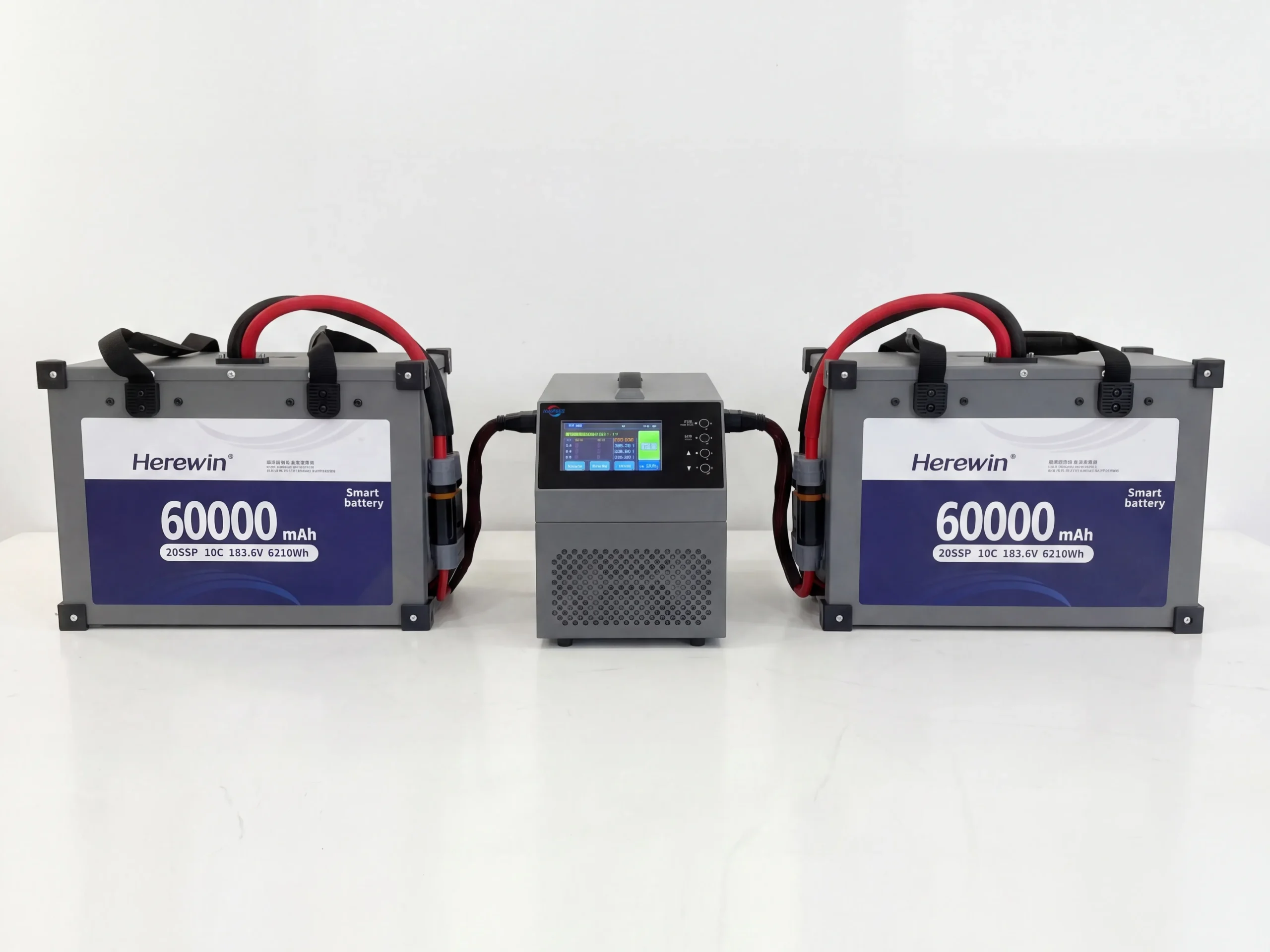
If you’re evaluating partners, it’s reasonable to ask for the battery-side view of BMS safety and monitoring architecture; a general reference point is Herewin’s BMS technology overview.
UAV Applications and Operational Scenarios
Protocol choices should be justified by mission constraints, not preference.
Agriculture, Logistics, and Aerial Cinematography
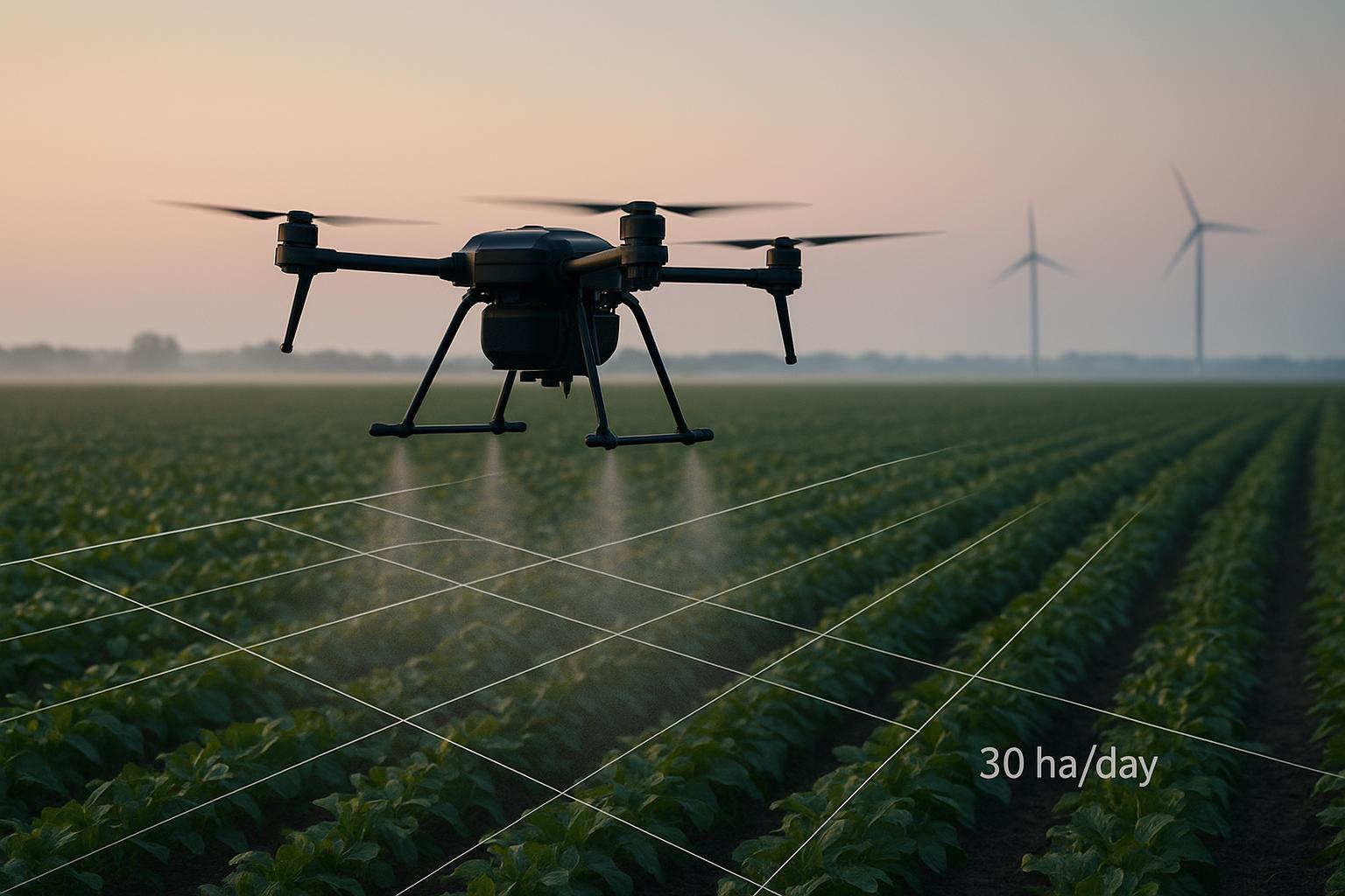
Agriculture: long duty cycles and repeated sorties make telemetry-driven maintenance (SOH trend) valuable; thermal conditions can be harsh.
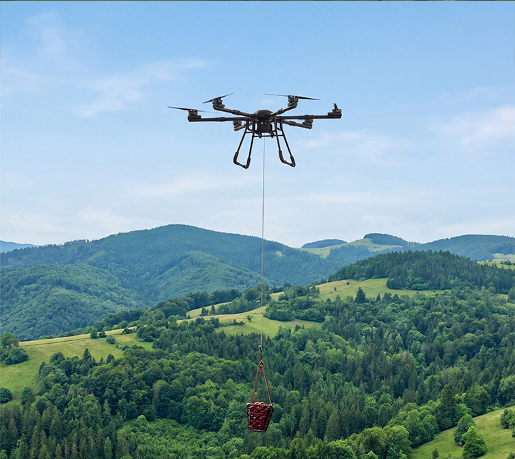
Logistics: route planning and reserve management depends on trustworthy SOC and predictable sag behavior.
Aerial cinematography: consistent power delivery matters for stable control and repeatable performance; you care about minimizing intermittent telemetry dropouts that cause conservative throttling.
Future Trends: 5G Connectivity and AI-Based Battery Diagnostics
Two trends are converging:
Connectivity (including cellular backhaul in some operations): pushes telemetry into fleet dashboards for remote monitoring and audit trails.
Diagnostics models: make SOH less of a single number and more of a pattern-based prediction (fault precursors, cell imbalance signatures, thermal anomalies).
The near-term implication: pick an architecture your team can log, validate, and scale—not just one that “works on the bench.”
Selecting the Right Battery Communication Strategy for Your UAV System
A robust UAV battery communication protocol strategy is the combination of:
Protocol (how data moves)
Data model (what you measure and how you validate it)
Integration logic (how the flight controller reacts under missing/invalid/stale data)
One practical way to keep integration on track is to draft a one-page interface contract for the battery → flight controller link—covering fields, update rates, validity flags, timeouts, and fallback limits. And if you’re evaluating OEM/ODM partners, ask for their documentation and integration support (for example, a supplier’s integration guide, interface control document, or sample telemetry mapping) so you can confirm that contract matches what they can actually deliver.
If you’d like a faster path to bring-up, Herewin’s engineering team can share integration-ready documentation (telemetry field list, alarm/fault semantics, and recommended update rates) and align it to your flight controller stack. Learn more about Herewin or reach out to discuss your UAV power requirements.