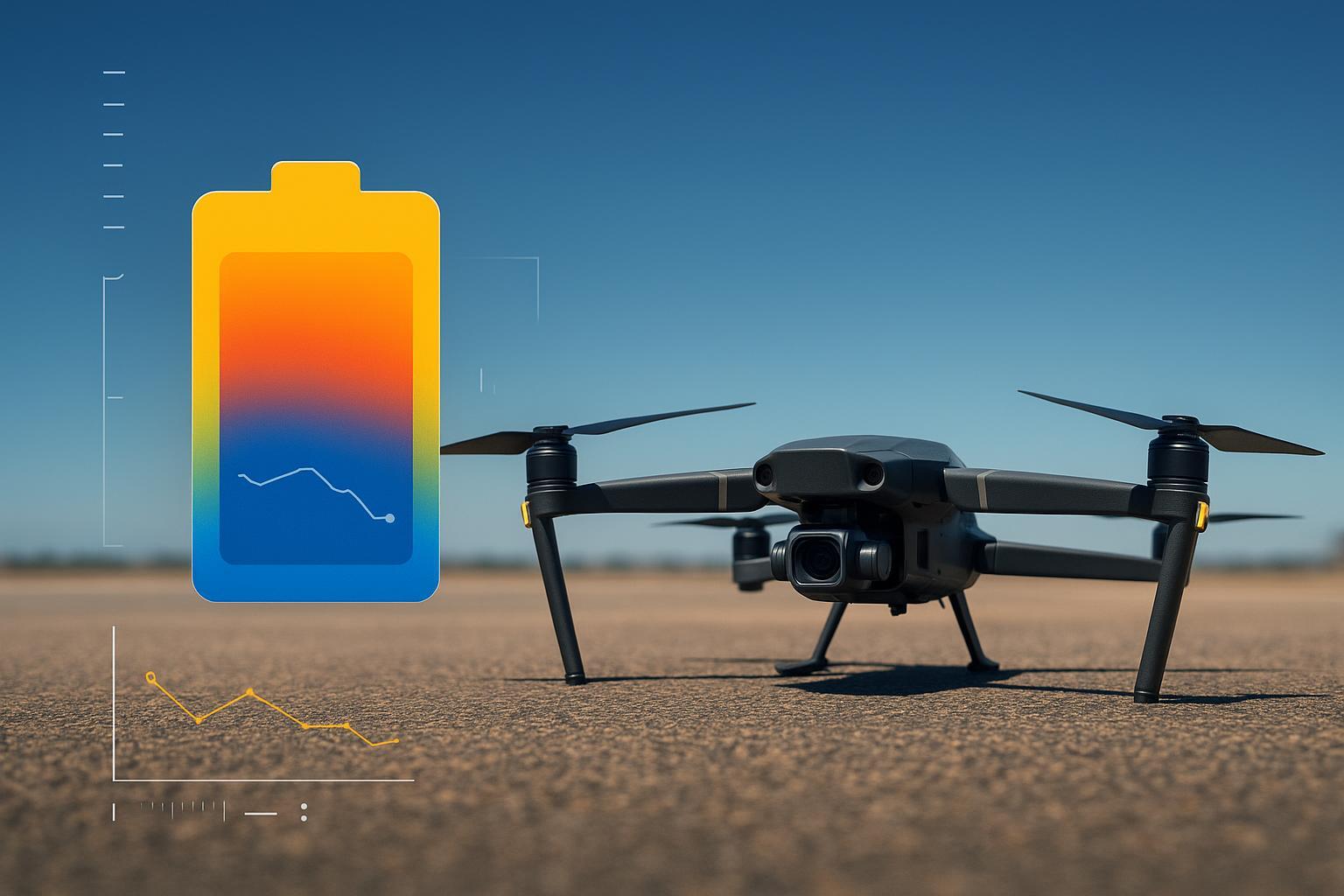


If your fleet hits the same wall every summer, it usually shows up as a repeatable pattern:
Deeper voltage sag on takeoff/climb at the same payload
Hot connectors or warm harness sections after landing
Earlier derating as the day goes on (same rotation tempo)
Shorter usable windows per pack and “aged overnight” behavior
Unpredictable power under high load even when the pack looks normal
If those look familiar, the issue is rarely “summer inconvenience.” It’s a power system operating closer to its thermal limits—with less margin for resistance growth anywhere in the path.
Spring flights look normal. Then summer arrives and the same aircraft starts acting underpowered: earlier derating, deeper sag on takeoff, warm connectors, and packs that seem to “age overnight” after a few weeks of tight rotations.
The mission didn’t change. What did change is the buffer your system was quietly relying on: thermal headroom.
Once thermal headroom collapses, every high-current event—fast charging, takeoff, climb, payload lift—runs closer to temperature limits. Small resistance growth in a harness, connector, or cell can become a threshold event.
If you’re seeing summer derating, noisy voltage telemetry, hot connectors, or shrinking usable windows per pack, you’re not dealing with “summer inconvenience.” You’re seeing the early stages of a predictable failure chain.
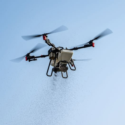
UAV overheating in summer: why it happens
Industrial UAV fleets don’t get to live inside a single, stable temperature envelope.
They run repeated high-power cycles, in direct sun, near dust, with mission tempo pushing packs from landing to charger to takeoff with minimal dwell time. Even when the air temperature looks “reasonable,” deck temperature, battery-bay temperature, and connector temperatures often aren’t.
To make the discussion concrete, the industrial platforms that struggle most in summer often share a similar operating profile (exact values vary by airframe, pack capacity, and mission profile):
Continuous high-rate discharge during heavy-lift hover: roughly 5C–8C
Field fast charging to compress turnaround: roughly 2C–4C
High current in the power path (platform-dependent): often ~80A–150A
In a 25°C test environment, the system gets “free cooling.” That stretches the time constant of every thermal failure mode, so voltage sag and temperature rise can look stable in the lab while becoming unstable in the field.
An illustrative, anonymized field-style comparison shows how quickly thermal headroom can collapse (exact numbers depend on sensor placement, airflow, sun load, and whether you’re measuring surface vs core):
25°C ambient: after an 8C heavy-load mission, the cell temperature reached about 42°C, then recovered close to ambient after ~8 minutes of rest.
38°C ambient: with the same mission profile, the cell temperature reached about 58°C, and after ~10 minutes of rest it was still around 52°C.
Same mission. Similar current. Very different starting point for the next cycle.
To make summer troubleshooting faster, cluster symptoms into decision triggers:
If voltage sag deepens on takeoff/climb at the same payload, resistance is rising somewhere in the power path. That can be cell internal resistance, but it’s often also harness/connector contact resistance.
If connectors come back noticeably hotter than the pack case, assume a connector/crimp/harness bottleneck until proven otherwise.
If derating starts earlier each day with the same rotation tempo, you’re in a heat accumulation loop (insufficient cooling reset between land → charge → takeoff).
If packs “look fine” but power becomes unpredictable under high load, treat it as a latent degradation signal (often resistance drift) rather than a single bad flight.
Thermal headroom is the gap between:
the temperature you start at, and
the temperature where your system must derate or shut down to protect cells, connectors, and electronics.
In summer, you start closer to the ceiling.
For typical lithium systems, performance is often strongest near room temperature, and long-term aging generally accelerates as sustained operating temperature rises. As a practical target, many teams aim to keep packs roughly in the 20°C to 30°C band when possible—then validate against the cell and aircraft OEM limits for their specific pack and duty cycle. NeoGraf summarizes why this matters in “Thermal Management in Batteries Used in the UAV and eVTOL Industries” (2025).
Those decision triggers map to three subsystems you have to diagnose in parallel:
the battery (internal resistance drift and degradation)
the harness and connectors (contact resistance and hotspots)
the operational heat loop (duty cycle and cooling reset)
UAV thermal failure diagnosis map
Use this as a fast decision layer: symptom → subsystem → verification → first action.
What you see in the field | Likely cause category | What to check first | First action |
|---|---|---|---|
Voltage sag suddenly worse on takeoff/climb (same payload) | Battery resistance drift or connector/harness resistance | Compare sag vs current across packs; check connector temps after landing | Log the sag curve; measure connector temperature asymmetry |
Connectors hotter than the pack case after the same mission | Connector/crimp/harness bottleneck | Look for discoloration/softening; check looseness/fretting marks | Re-terminate/replace suspect connector; verify strain relief |
Derating starts earlier each day with the same rotation tempo | Operational heat accumulation loop | Track pack temp at landing and before charge; look at cooldown time | Add a real cooling reset (shade/forced air) or reduce charge rate |
Pack looks normal but power becomes unpredictable under high load | Latent cell degradation (SEI / IR rise) | Track internal resistance trend if available; compare time-to-derate pack-to-pack | Retire outliers early; lower peak load/charge stress |
Harness hotspot near 60–70°C in flight logs or after landing | Wiring thermal risk center | Inspect insulation/housings; check for hardening/cracks | Replace with higher-temp wire/connector; reduce peak current until fixed |
Summer doesn’t just make things hotter. It breaks the rhythm most high-utilization fleets rely on.
In cooler weather, many operations unknowingly let the environment do the cooling reset:
fly hard
land
wait “a little bit”
charge
repeat
In summer, that sequence turns into a trap. You land hot, you charge hot, and you take off hot again—before the pack core and the interconnect path have actually reset. The baseline temperature ratchets upward across the day, and a profile that felt stable in the morning starts derating by noon.
Summer failures are often the result of cumulative heat saturation, not a single overheat event.
A useful way to think about this is that battery heating comes from two buckets:
Ohmic heating (I²R losses in cells and interconnects)
Polarization-related heating (electrochemical inefficiency under high-rate charge/discharge)
In mild conditions, you can sometimes “separate” them with time (fly, cool, then charge). In summer rotations, you often stack them: discharge heat hasn’t cleared before fast charge adds another heat pulse.
UAV connector overheating and high-current wiring heating: the summer failure chain
Most “battery failures” in summer are actually a power-path failure chain that shows up at the battery.
Ambient rises → harness resistance rises → localized hotspot near a connector/crimp can climb into the ~60–70°C range (a common warning band, depending on insulation rating and connector spec) → insulation softens and ages → intermittent micro-shorts → a sudden voltage collapse under load → BMS derating or in-air power loss.
The reason this is so dangerous is that it often looks like normal variability—until you hit a threshold.
A connector/harness hotspot doesn’t fail gracefully. Once contact resistance starts creeping up (oxidation, loosened fit, a marginal crimp), it can turn into a heat amplifier: more resistance creates more heat, and more heat accelerates the damage.
The key mechanism is simple: heating scales with I²R. At high current, even a small resistance increase in a connector pin, crimp, solder joint, or distribution terminal can create a disproportionate temperature rise. Copper resistance also increases with temperature (a common rule-of-thumb is ~4% higher resistance for every +10°C), so summer turns small electrical weaknesses into visible hotspots.
To keep root-cause thinking honest, treat the harness path as part of this chain, not a standalone culprit. It’s a system: wire gauge, length, termination process, strain relief, vibration exposure, and connector interface condition.
Practical checks that catch problems before the event:
compare left/right and pack-to-pack connector temperature after the same mission (asymmetry is a red flag)
inspect for discoloration, softening, or deformation around housings and heatshrink
check for looseness or fretting marks that indicate vibration wear
log voltage sag vs current at takeoff across days; a drifting sag curve often shows resistance growth earlier than alarms do
Early signs usually appear first as:
hotter-than-normal connectors after landing
noisier voltage telemetry and deeper sag on takeoff/climb
earlier derating at the same payload and mission profile
Drone voltage sag under high temperature load: what changes inside the battery
High temperature plus repeated high-current cycling doesn’t just “reduce performance.” It changes the cell.
A key mechanism is SEI (solid electrolyte interphase) layer growth and instability. Under heat and high-rate cycling, the SEI can thicken abnormally and become less stable. The practical result is an irreversible rise in internal resistance.
This is where many teams get caught: it can be a latent failure. Packs may show no obvious swelling and no dramatic alarms, yet the internal resistance has moved enough that high-power events become unpredictable.
That creates the worst feedback loop in summer operations:
resistance rises irreversibly
the same current produces more heat and deeper voltage sag
hotspots become easier to trigger in connectors and harnesses
packs hit thermal limits earlier, derate sooner, and age faster
Once the cell has shifted into this higher-resistance state, “resting it” rarely restores the original power capability. Operationally, it looks like a pack that still charges normally but collapses under load—and reaches early retirement faster than the cycle count would suggest.
Why drones derate in hot weather: operational heat loops that break uptime
This is also the operational pain point most teams underestimate: a “high-utilization day” isn’t one demanding mission. It’s a sequence of missions where the system never fully returns to baseline.
If your SOP is built around minimal dwell time, summer forces a choice:
add a real cooling reset (shade, forced air, a cooling base), or
accept that derating and early retirement will become part of the operating cost.
A short “wait time” is not a cooling protocol.
If the pack core is still hot, charging pushes it into a regime where aging accelerates and safety margin shrinks. Multi-pack rotation only helps if the rotation includes a real thermal reset window (shade, forced air, or clear duty-cycle limits).
When ambient air is hot, convection doesn’t disappear, but its value drops. You’re trying to move heat into air that is already close to component temperature, so “wind cooling” hits hard limits above roughly the mid-30°C range.
Common misconceptions that create avoidable failures
“Battery heating during fast charge is normal” (dangerous assumption)
Some temperature rise is expected. Uncontrolled temperature rise is not.
As FPV educator Oscar Liang notes, if a LiPo pack gets warm while charging at 1C, you should stop immediately—it’s a key warning sign that something is wrong. See “When to Retire/Dispose LiPo Battery?”.
In high-tempo summer rotations, that “warm-at-charge” warning can quickly show up as unpredictable voltage sag, earlier derating, or sudden power instability in the next few duty cycles, even if the pack looks normal at rest.
If charging repeatedly produces packs that are uncomfortably hot to touch (or require long cooldowns before flight), treat it as a stability problem, not a routine side effect. It often signals that the system has lost thermal headroom—because the cells, interconnects, or cooling reset window can no longer keep heat in a safe, repeatable range.
“If the BMS doesn’t alarm, it’s safe” (hidden blind spot)
A BMS is a protection system, not a guarantee.
Depending on sensor placement, it may not detect the hottest point early enough—especially if the hotspot is at a connector, crimp, distribution terminal, or inside the cell core. Surface temperature can look acceptable while the core is running hotter (a commonly observed gap can be ~8–12°C in hard-duty, hot-ambient scenarios, but it depends on cell format, thermal path, and where sensors are placed).
If you need decisions you can defend, build a simple measurement plan: verify temperatures with calibrated sensors and check more than one location (pack surface, bay air, connector housing, and at least one high-current termination point).
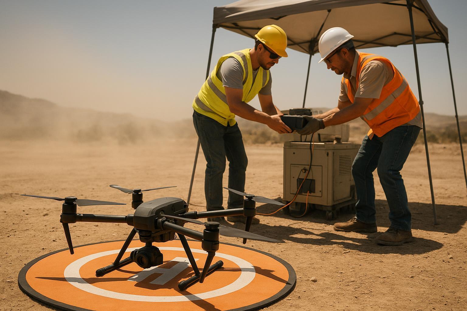
Engineering solutions for high-temperature UAV operations
Teams usually overcorrect in one of two ways: ban fast charging entirely (killing utilization), or keep doing the same thing and accept failures as “summer reality.” Both are avoidable.
Operational SOP adjustments
Start with controls you can implement in a week. Treat these as reference starting points—you still need to validate them against your aircraft and battery OEM limits, local conditions (sun, wind, staging surface), and your own measured temperatures:
enforce a cooldown gate before charging (based on measured temperature, not a fixed time)
as a reference, consider a cooldown window of ~15 minutes or more after heavy-lift missions before fast charge, if your measurements show heat isn’t clearing fast enough
reduce charge current during the hottest hours if you have no thermal infrastructure
when ambient is above roughly 35°C, consider stepping down from your “rush” charge profile; as a reference, fleets often test dropping from around 3C to ~1.5C–2C during peak-heat windows
avoid heavy-lift missions during the most extreme heat hours if you can shift work earlier/later in the day; as a reference, some teams avoid ~11:00–16:00 in high-sun, high-surface-temperature environments
The goal isn’t to slow operations forever—it’s to keep the pack in a stable, repeatable thermal regime so you don’t trade today’s throughput for unpredictable power and early pack retirement tomorrow.
Hardware upgrades that often fix the real bottleneck
If your bottleneck is interconnect heating, no cell upgrade will fix it.
upgrade connectors for contact stability at real peak current
use wire gauge, length, and termination processes that match true peak current
add thermal interface materials where they meaningfully spread heat to the structure
use a forced-air cooling base or shaded staging area to create a real cooling reset
BMS and control strategy
High-availability fleets often need a different philosophy:
early derating to stay inside a stable regime
trend-based monitoring (temperature rise rate, resistance drift) instead of waiting for hard thresholds
This is where “smart battery” integration becomes real value: not because it’s smart, but because it makes operations predictable.
What this means for industrial UAV operators
In summer, your limiting factor often isn’t nominal capacity or headline C-rating. It’s the thermal margin that determines whether the system can hold voltage and power repeatedly, without derating, without accelerated aging, and without safety exposure.
Pushing peak throughput (fast charge + maximum payload + minimal downtime) has a cost. Make that cost explicit:
how much throughput do you gain?
what is the extra battery replacement rate?
what is the downtime risk?
what is the warranty and safety exposure?
When you quantify the trade, the “right” operating window becomes clearer.
“Thermal intelligence” should mean one thing: the system can predict when it is leaving a stable regime. That requires visibility into temperature, resistance trends, and how fast the pack is accumulating heat under your specific duty cycle.
From thermal failure to stable power systems
If your fleet is seeing summer derating, connector heating, voltage sag, or swelling, treat it as a power-system design problem—not a battery brand problem. Stay inside the aircraft and battery OEM limits for charge rate, discharge rate, and temperature. Then verify what’s actually happening with calibrated measurements in more than one place—pack surface, battery-bay air, connector housings, and at least one high-current termination point.
If your utilization model depends on fast charge and repeated high-load cycles, the next step is to align the cell, pack, connector/harness sizing, and thermal reset window as one integrated spec.
To discuss your duty cycle and get a practical recommendation for a high-temperature, high C-rate UAV battery build, contact Herewin here: Herewin Contact.