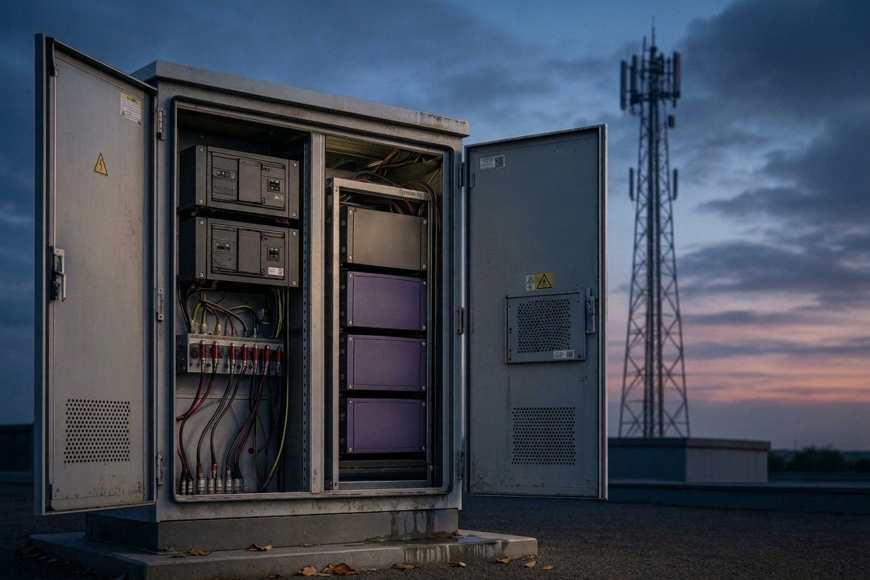


A mobile BESS (mobile battery energy storage system) is a transportable power subsystem—a factory-integrated unit designed to deliver stable AC power for temporary, backup, and off-grid or weak-grid sites.
For EPC teams, the real differentiator is scope clarity: a deployment goes faster when the unit arrives with a defined electrical envelope (inputs, outputs, protection, communications) and a commissioning-ready control stack.
Key takeaways for EPC and delivery teams:
Define the integration boundary early. Lock the single-line diagram boundary and the OEM/EPC scope boundary together.
Ask for acceptance evidence—not claims. Require a FAT procedure, pass/fail criteria, and exportable event logs.
Make protection and controls deterministic. Document trip hierarchy (BMS ↔ PCS ↔ EMS) and mode-transition authority.
Engineer the interface, not the connectors. Align grounding, comms mapping, and upstream coordination assumptions.
What Is a Mobile BESS and How It Compares to Other Systems
From Battery Pack to Independent Power System
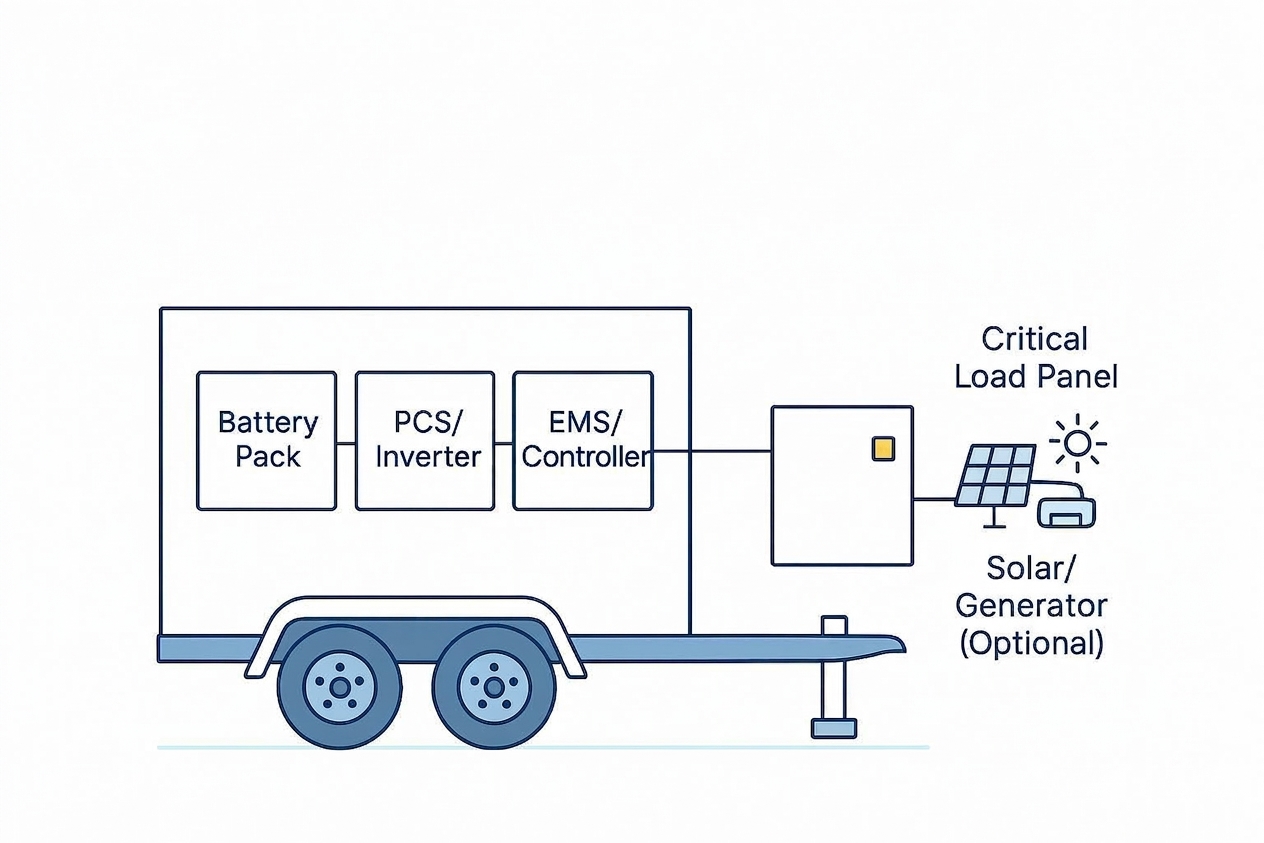
A battery pack becomes an independent system only after you add three layers:
Battery-level safety and control (BMS + contactors + protection)
Power conversion (PCS to move energy in/out of the DC battery)
System-level supervision (EMS/controller to enforce modes, priorities, and limits)
In practice, “mobile” often overlaps with terms like portable BESS or trailer-mounted BESS.
The engineering question is the same: what is factory-integrated, and what is left to the EPC scope?
Off-Grid Capability: When the Grid Is Not an Option
In off-grid and weak-grid projects, the unit is frequently asked to do more than energy shifting:
stabilize a microgrid with fluctuating loads
buffer generator transients (reducing step-load stress)
provide ride-through for critical loads during source transfer
That pushes attention toward controls (modes, black-start sequence, priority loads) and toward the quality of the interface between EMS and PCS.
Why Integration Matters for Faster Deployment
“Fast deployment” only happens when the integration contract is explicit:
who owns the single-line diagram boundary (terminals, neutral/ground, protection)
what comms are required (Modbus/TCP, CAN, Ethernet, hardwired I/O)
what acceptance tests are expected (FAT/SAT, alarms, trip logic, event logs)
System Lifecycle and Integration: What Makes It Deliverable
For EPC teams, a mobile BESS becomes a deliverable system only when the lifecycle is explicit—not implied. A practical engineering loop looks like this:
Design specification: load profile assumptions, single-line, grounding method, protection philosophy, comms point list, and control priority rules.
Factory integration: battery + PCS + EMS + auxiliaries integrated to a defined electrical envelope (terminals, interlocks, E-stops, remote shutdown).
FAT: documented functional checks (modes, alarms, trip logic, event logs, comms mapping), plus power-quality and step-load tests where applicable.
Transport & installation: mechanical constraints, cable/connector scope, earthing, and site interfaces (genset/PV/grid/ATS).
SAT / commissioning: interface verification on-site (metering polarity, CT/VT mapping, protection coordination with upstream devices, and mode transition behavior).
Operation & maintenance: procedures for fault triage, firmware/version control, replacement parts, and remote monitoring responsibilities.
A useful way to reduce schedule risk is to write down OEM vs EPC boundaries in the same place as the single-line boundary.
Be explicit about who supplies settings files, who owns protection coordination, who signs off on FAT/SAT results, and what the acceptance criteria are (pass/fail thresholds, required logs, and the exact test steps).
Core Components of a Mobile BESS
PCS (Power Conversion System): Bi-Directional Power Control
The PCS is the electrical “valve” of the system. It governs how power moves:
charge: AC/DC source → DC bus → battery
discharge: battery DC → inverter → AC load bus
For EPC engineers, PCS is where many integration failures show up:
protection coordination issues (fault current behavior vs upstream breakers)
power quality conflicts with sensitive loads
instability during mode transitions (generator + storage sharing)
What procurement teams often miss is the validation question: how do you prove the PCS is stable in your operating modes? Practical acceptance evidence includes:
Transient response: step-load response time, overshoot/undershoot limits, and recovery behavior.
Fault clearing behavior: how it reacts to downstream faults, what it trips on, and how it coordinates with upstream protective devices.
Waveform quality range: harmonic distortion and voltage/frequency regulation under representative loads.
Practical evaluation questions:
What modes are supported and documented?
What are the control interfaces (setpoints, droop settings, ramp limits)?
What events are logged, timestamped, and exportable?
What FAT/SAT test cases demonstrate stability, protection behavior, and power quality in those modes?
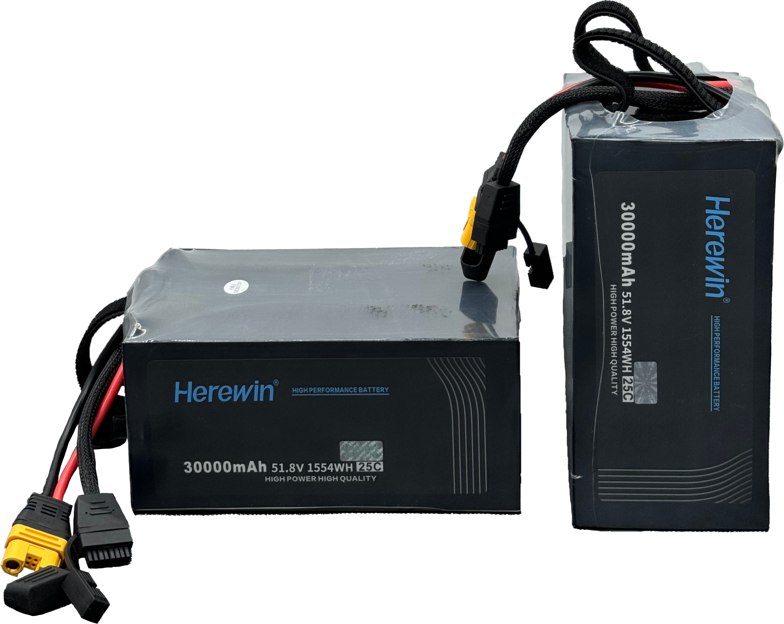
Battery Pack: LFP for Long-Term Reliability
For industrial deployments, LFP (LiFePO₄) is commonly chosen when safety margin and cycle life are prioritized over maximum energy density.
What matters more than chemistry labels is pack-level engineering:
cell matching and balancing approach
thermal design and sensor placement
fault isolation strategy (string/rack level)
EMS (Energy Management System): Monitoring, Dispatch, and Predictable Priority
The EMS/controller is where “it should work” becomes “it does work in your project.” It typically:
enforces operating modes (charge/discharge/standby/islanding)
prioritizes loads (critical vs non-critical)
coordinates sources (PV, generator, utility) and the PCS
exposes monitoring to SCADA/remote O&M
For engineering teams, the key is not that the EMS is “smart,” but that it is predictable. A mobile BESS should document a simple control hierarchy:
Source priority: which source leads in each mode (e.g., PV-first vs generator-first), when the battery is allowed to charge/discharge, and what happens at SOC limits.
Load priority / shedding rules: which feeders are critical, what the shed thresholds are (frequency/voltage/SOC), and how recovery is staged.
Mode transition logic: who has control authority during grid↔island transitions and generator start/stop, including ramp limits and hold times to avoid hunting.
If SOC estimation is noisy or comms mapping is incomplete, dispatch becomes unstable and operators lose trust.
Output Interfaces: Engineering Compatibility, Not Just Connectors
Treat output interfaces as an engineering compatibility problem, not a connector problem. A useful framework is to classify interface requirements into three buckets:
Electrical compatibility
nominal AC voltage and frequency range
continuous vs surge power behavior
allowable load types (motors, rectifiers, UPS front-ends) and any known limitations
Protection coordination
neutral/grounding scheme expectations and earthing method
protection device coordination expectations (fault contribution behavior, breaker/fuse assumptions)
Operational constraints
black-start behavior and transfer logic
any mode-specific limits (ramp rates, minimum genset loading, SOC guard bands)
If a vendor can’t provide an auditable protection philosophy (BMS trips, contactor behavior, pre-charge logic, fault states), assume on-site debugging time will land on your EPC team.
A good protection philosophy reads like a hierarchy, not a collection of features:
Battery-layer protection (BMS): cell/module limits, contactor open logic, and pre-charge sequencing.
PCS-layer protection: inverter/converter fault states, current limits, and how it behaves during abnormal grid/genset conditions.
Coordination layer: deterministic rules for how BMS and PCS trips interact (who trips first, what resets are allowed, what is latched).
System-level protection logic: interlocks, E-stop, remote shutdown, and system fault handling in the EMS.
Fault hierarchy and trip logic: clear priorities (warning → derate → isolate → trip), with event logs that can be audited after a trip.
Parallel Scalability: Capacity Expansion and Redundancy
Parallel operation is not just adding kWh. For delivery teams, it’s about resilience and controllability:
In engineering terms, multi-unit paralleling is a distributed control problem: synchronized voltage/frequency references, deterministic load sharing, and defined behavior when one node drops out.
Is parallel operation supported with documented synchronization behavior?
What happens when one unit trips—does the remaining system degrade gracefully?
Are there deterministic rules for load shedding and recovery?
What Differentiates a Delivery-Ready Mobile BESS
The fastest way to make a good procurement decision is to separate features from verifiable delivery behavior. A “high-performance” mobile BESS is usually not defined by kWh alone—it’s defined by whether the vendor can show deterministic controls, auditable protection logic, and test artifacts that match your site interfaces.
Here’s a practical basic vs delivery-ready comparison you can use in vendor evaluations:
Decision dimension | Basic unit | Delivery-ready unit |
|---|---|---|
PCS stability evidence | Claims of “stable” operation, limited test detail | Defined step-load limits, transient response targets, and documented test cases with logs |
Fault / protection behavior | Generic protection list | A written protection philosophy with trip hierarchy and coordination rules (BMS ↔ PCS ↔ system) |
EMS determinism | “Smart EMS” language without priorities | Source priority + load shedding rules + mode transition authority documented and testable |
Interface boundaries | “Connect and power on” assumptions | Single-line boundary, grounding expectations, and upstream coordination assumptions are explicit |
Comms deliverables | Partial register map, unclear timestamps | Point list + register map + timestamped events/alarms + clear SCADA integration workflow |
FAT/SAT artifacts | Informal demos | FAT procedure + pass/fail criteria + SAT checklist + required logs for sign-off |
Parallel operation | “Supports paralleling” | Documented synchronization/load-sharing method and defined degradation behavior when a unit trips |
If you need one guiding principle: a mobile BESS is less about energy, and more about avoiding failure at the integration boundary (controls, protection, comms, commissioning).
How a Mobile BESS Works: The 4-Step Energy Flow
Step 1: Energy Harvesting (Solar or Generator Input)
A typical deployment charges from one or more sources:
PV (directly or via an upstream PV inverter)
generator (often the dominant off-grid source)
utility (when available)
Key integration question: where is the control authority? If the generator controller, EMS, and PCS all “think they’re in charge,” commissioning becomes a negotiation.
Step 2: Conversion and Energy Storage
Charging is never 100% efficient. You have conversion losses in the PCS and losses in the battery. At the architecture level, what matters is that limits are enforced consistently:
max charge/discharge current
temperature-based derating
SOC guard bands
Step 3: Power Supply to Critical Loads
When discharging, the PCS provides the AC waveform and the EMS decides how much and to whom.
In practice, critical-load outcome depends on response time to step loads and stability during transitions.
Step 4: Automated Backup for Continuous Operation
The value is often continuity—power during transfers, outages, and maintenance windows.
For safety framing in US contexts, many projects reference UL methods and listings as part of risk management; UL explains the purpose of its UL 9540A test method for evaluating thermal runaway fire propagation hazards. (Applicability depends on jurisdiction and scope.)
Where Mobile BESS Projects Fail in Real Deployment
When deployments go sideways, the root cause is rarely “the battery.” It’s usually a controllability or boundary-definition issue that shows up during commissioning or in the first weeks of operation—especially in off-grid and weak-grid sites.
Common failure modes to watch for:
Generator hunting or oscillation: poor droop/ramp coordination between genset governor, PCS, and EMS causes unstable power sharing.
Mode transition instability: grid↔island or generator start/stop transitions create brownouts, nuisance trips, or load resets.
SOC drift and dispatch surprises: SOC estimation error or missing temperature/derating logic leads to unexpected early shutdown or unavailable power.
Comms mapping gaps: wrong scaling, missing timestamps, or incomplete point lists make SCADA visibility unreliable and slow down fault triage.
Nuisance trips from protection mismatch: upstream breakers, RCD/GFDI logic, and inverter fault behavior aren’t coordinated, so minor events become full trips.
Parallel desynchronization: multi-unit systems don’t share load deterministically, or they fail to degrade gracefully when one unit isolates.
What operators typically see first is not a single catastrophic alarm—it’s patterns: frequent resets, contradictory statuses across PCS/EMS/BMS, or events that can’t be reconstructed because logs are incomplete.
Basic Sizing Logic: How Long Can a Mobile BESS Run?
Power (kW) vs. Energy (kWh): Key Differences
kW is how fast you can deliver energy.
kWh is how much energy you have stored.
A common field failure is to size for kWh (runtime) and discover you’re short on kW (transients, motor starts, spikes).
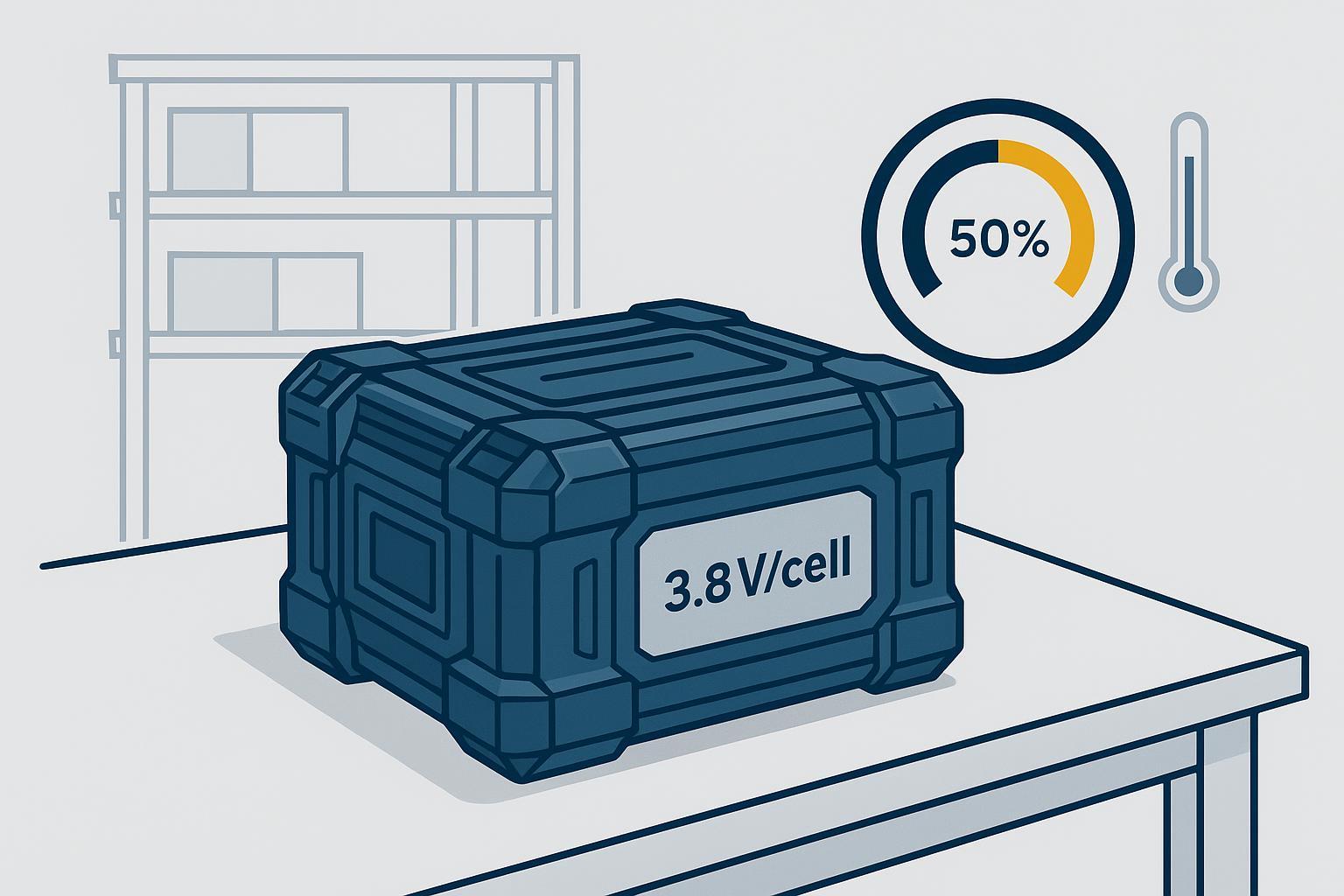
Real-World Factors: Efficiency, DOD, and Temperature
Runtime in the real world is reduced by:
conversion efficiency
usable SOC window (DoD policy)
temperature-driven derating
auxiliary loads (HVAC, controls, heaters)
A Simple Runtime Formula for Mobile BESS Sizing
Use a transparent estimate:
Runtime (hours) ≈ Usable Energy (kWh) × System Efficiency ÷ Average Load (kW)
Example assumption (illustrative only):
Usable energy = 200 kWh
Efficiency = 0.90
Average load = 50 kW
Runtime ≈ 200 × 0.90 ÷ 50 = 3.6 hours
Industrial Applications of Mobile BESS
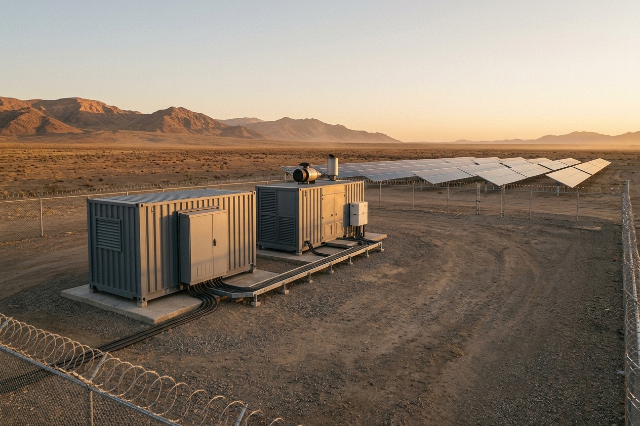
Remote Operations: Mining, Construction, and Oil & Gas
Remote sites care about predictable uptime, fewer generator maintenance events, and stable power for mixed loads. Storage can act as a buffer that turns a “spiky” profile into something generators handle more efficiently.
Critical Infrastructure: Hospitals and Data Centers
In critical facilities, the architecture question is rarely “can it provide power?” It’s how it behaves during transfer events, what the failure modes look like, and what is required for acceptance testing and audits.
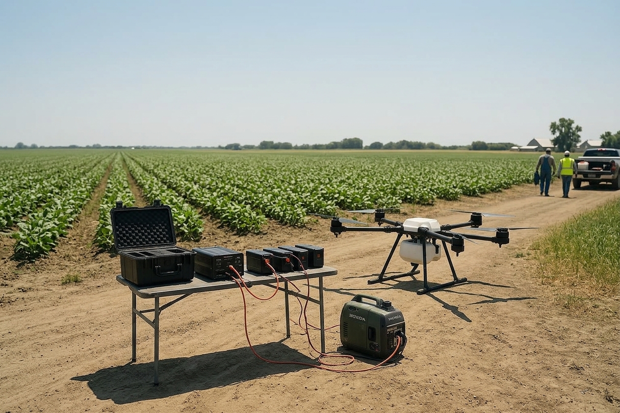
Temporary Power: Mobile Medical and Field Operations
Temporary deployments reward integration completeness: fast energization with minimal on-site wiring, clear operator alarms, and repeatable commissioning.
Procurement Checklist vs. Engineering Acceptance Checklist
A procurement checklist asks “does it have the feature?” An engineering acceptance checklist asks “can we verify the behavior and sign it off?” For mobile BESS projects, the second one is what protects schedule.
A simple rule: every major claim should map to an artifact you can review and approve—single-line boundary documents, protection philosophy, comms point list/register map, FAT procedures with pass/fail thresholds, SAT commissioning steps, and timestamped event logs. If the vendor can’t provide those deliverables early, expect on-site debugging to expand EPC scope.
How to Choose a Mobile BESS: Key Performance Factors
Key Performance Indicators for Procurement Evaluation
Focus on KPIs that reduce integration and commissioning risk:
Interface definition: single-line boundary, protection philosophy, grounding scheme
Controls documentation: operating modes, ramp rates, droop settings, setpoint list
Comms package: point list, register map, alarms/events with timestamps
Thermal strategy: derating logic and operator visibility
Safety evidence: test reports/listings relevant to the jurisdiction (avoid vague “compliant” language)
Warranty boundaries: what is covered (cells/modules/PCS/controller), exclusions, and fault triage workflow
If you’re evaluating vendors for commercial/industrial deployments, Herewin’s Commercial & Industrial Energy Storage Solutions page is a useful starting point for understanding their ESS scope.
Mobile BESS as a Flexible Energy Asset
A mobile BESS is flexible only when it is engineered as a complete system: battery safety, bi-directional power conversion, and supervisory controls—plus clear interfaces.
If you want to pressure-test a vendor’s integration readiness, start with a checklist approach (interfaces, comms, modes, acceptance tests) and adapt it to your mobile deployment boundary. Herewin’s C&I BESS selection and risk management guide is a practical reference for how to structure those questions.