


If your delivery drones spend more time tethered to chargers than in the air, the primary constraint is not energy density, but turnaround efficiency. In high-frequency last-mile delivery networks, excessive charging dwell time directly impacts fleet scalability and asset utilization.
This article focuses on high-cadence logistics operations, where drones may perform dozens of sorties per day and ground turnaround becomes the dominant operational bottleneck. In lower-duty missions—such as inspection or surveillance—conventional fast charging may remain a practical and cost-effective option.
Within this operational scope, we distill field-proven engineering practices for drone battery systems, focusing on two technical pillars: high-durability quick-swap hardware and cloud-integrated BMS telemetry that ensures the SOC/SOH precision required for automated scheduling. We analyze these strategies through a data-driven ROI model and an urban “lunch-rush” operational vignette.
Quick‑swap for 24/7 operations: eliminating the charging gap
Charging imposes a fixed “dwell time” on fleet operations. Even optimized fast-charge windows typically span tens of minutes, a delay that compounds across multiple sorties and necessitates the over‑provisioning of airframes. Quick‑swap technology replaces this downtime with a 30–120 second exchange, allowing aircraft to return to service immediately while depleted packs recover via stabilized, battery‑friendly charging protocols.
However, from an operational durability perspective, the high cadence of last-mile delivery means swap interfaces may undergo thousands of mating cycles per month. At this scale, connector durability and mechanical alignment precision become the primary limiting factors for fleet MTBF.
Suppose a standard route requires 14 minutes of flight and 3 minutes of ground handling. With a 30-minute on-pad recharge, a single drone yields approximately 1.5 sorties per hour. Implementing a 60‑second quick-swap increases this to ~3.5 sorties per hour—a 2.3× increase in operational throughput from the same airframe asset. This efficiency gain is why leading last-mile solutions treat quick‑swap as a systemic architecture rather than a mere component selection.
High-Durability Interconnects: Engineering for Quick-Swap Reliability
High-frequency swapping success depends entirely on the reliability of the interconnect architecture. Currently, two dominant approaches prevail in the industry: spring-loaded contacts (Pogo Pins) and ruggedized blind-mate power connectors equipped with alignment funnels. To ensure fleet uptime, technical specifications must move beyond static datasheet values to focus on dynamic test evidence under harsh-duty standards.
Validation Benchmarks for Interconnects
When auditing vendors, request test reports aligned with the EIA-364 and IEC 60512 standards families. Industry benchmarks for high-quality contacts typically require a contact resistance of ≤20 mΩ. Key parameters should include:
Durability Cycles: Validated per EIA‑364‑09 or IEC 60512‑5 (Test 9a).
Contact Resistance: Low-level circuit resistance (LLCR) per EIA‑364‑23.
Environmental Integrity:IP65-rated protection is a peer requirement to mechanical cycle life. Environmental contaminants such as rain, salt spray, and abrasive grit can trigger accelerated dielectric breakdown or contact oxidation long before mechanical wear becomes a factor.
Design Requirements for Last-Mile Operations:
Plating and Geometry: Specify gold-over-nickel composite plating thickness appropriate for the mission’s peak current density. Utilize blind-mate geometries with chamfered funnels designed to facilitate smooth engagement even with a horizontal displacement of ±3mm and an angular deviation of ±5°, preventing scuffing of the contact surfaces.
Instrumented Maintenance:Implement bench-test protocols to track resistance drift and thermal rise. By logging milliohm (mΩ) changes against cycle counts, maintenance personnel can identify outliers and perform proactive refurbishment before field failures occur.
Core Performance Targets:
Cycle Life: ≥5,000–10,000 mating cycles, with post-test resistance drift remaining within defined power-loss budgets.
Thermal Stability: Temperature rise must be maintained at ≤30°C under the highest continuous current during takeoff/hover.
Mechanical Compliance: Utilize floating mounts or compliant features to prevent abnormal pin wear caused by lateral loads.
Engineering Note :Standard EIA/IEC testing provides a solid foundation but often fails to simulate the extreme stressors unique to high-voltage 12S (44.4V) logistics. To address this, we utilize the AS150U blind-mate interface with integrated anti-spark logic. This ensures the mechanical integrity of the connection far outlasts the 500–800 mission cycles typical of current high-energy cells. For fleets scaling with our 2026 Semi-Solid series, this interface remains pristine even as the energy asset extends toward 1,000+ cycles, significantly lowering long-term TCO for fleet operators.
Cloud-Connected BMS for Last-Mile Drones: Accurate SOC & Fleet Management
Your quick‑swap hardware is only as good as your scheduling certainty. Precision SOC/SOH—fused from coulomb counting, per‑cell voltages, and temperature—prevents mid‑mission surprises and unlocks tight pad choreography.
The KPI of Dispatch: SOC Accuracy
For fleet operators, raw data sampling is merely a baseline; SOC accuracy is the definitive KPI. In high-cadence logistics, aim for an SOC indication error within ± 3% across the working temperature band. This precision is the difference between confident, tight routing and inefficient, over-buffered flight paths. To achieve this, advanced BMS architectures utilize model-based filtering (such as Extended Kalman Filters) to keep error bounded as the pack ages.
Operational Sampling and Telemetry Standards
An in-flight sampling cadence of 1 Hz is the industry baseline: fast enough to ensure dispatch logic remains accurate, yet light enough to run reliably across long missions and restricted RF backhaul. The goal of high-fidelity telemetry is to avoid two costly outcomes:
Premature Low-Battery Alerts: Which artificially restrict fleet range and revenue.
Over-Optimistic SOC Estimates: Which force mid-route aborts or emergency landings.
Integration Strategy: From Vehicle to Cloud
Cloud integration is an extension of the vehicle’s avionics. Successful deployments rely on robust physical interfaces—CAN or RS485—and standardized data models to prevent mapping errors. A high-fidelity telemetry framework tracks two operational states.
Real-Time Mission Integrity (In-Flight, ≈1 Hz): This layer prioritizes flight safety via synchronized Per-Cell Voltages and Current. This granularity is critical for detecting “soft failures”—where a single cell exhibits abnormal voltage sag under load, even if the total pack voltage appears healthy. Fusing this with SOC/SOH estimates enables dynamic, energy-aware routing.
Asset Traceability and Recovery (On-Pad, 0.2–1 Hz): When a battery enters a hub, focus shifts to reliability. Logging
Swap_Station_IDdanCharger_Stateallows operators to correlate degradation with specific hardware. This enables automated triage: identifying charging bays that cause thermal stress and ensuring only packs with validated Internal Resistance (IR) are released for the next sortie.
Implementation: From Telemetry to Operational Business Rules
To move beyond data collection into active fleet management, the telemetry payload should be translated into three objective business rules to ensure every swapped pack is a mission-capable energy asset:
Launch Gate: Only dispatch packs that satisfy minimum SOC requirements, fall within the validated temperature window, and maintain a “fault-free” status. Each mission should include a weather-adjusted landing reserve (typically a 15% SOC buffer).
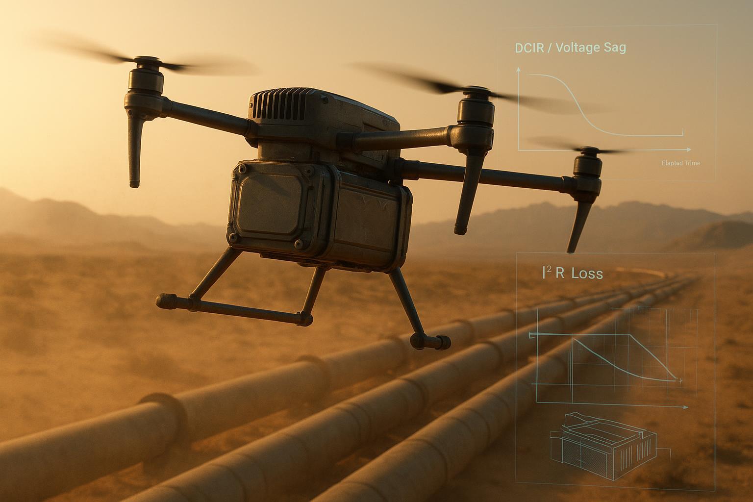
In-Flight Guardrails: Configure automated triggers for a controlled return-to-base if voltage sag or DCIR trends exceed established thresholds. This is particularly critical during high-discharge maneuvers (takeoff/hover), where a sudden increase in DCIR can lead to catastrophic power loss.
Swap-Hub Triage: Implement an automated quarantine for any pack whose SOH drops below the policy floor or whose DCIR exhibits a 25% rise relative to the fleet median at similar cycle and temperature bands.
Reference Standards for Integration
For organizations requiring external baselines for sensor cadence and estimation logic, we recommend consulting:
Parrot AirSDK: For standard 1 Hz battery sensor telemetry fields.
Analog Devices Technical Notes: Regarding Coulomb counting fused with OCV models and EKF approaches.
Catatan: While vendor SDKs provide a baseline, fleet contracts should remain centered on internal acceptance tests and standardized telemetry definitions. Herewin’s scope in this guide is the battery pack and its BMS/telemetry layer; physical swap-station mechanics and site infrastructure are typically delivered by the fleet operator or a station integrator.
Swap Hub vs Fast Charging: Sample ROI Analysis for Last-Mile Drones
Technical superiority is irrelevant if it does not translate into a superior bottom line. To evaluate the commercial viability of high-frequency swapping, operators must look beyond initial CAPEX and analyze the Total Cost per Delivery (TCPD).
The following worked example uses a 12S 22 Ah (976 Wh) configuration—the common configuration for heavy-lift last-mile delivery—to compare a managed swap-hub protocol against on-pad fast charging.
Catatan: All numerical values in this ROI model are illustrative, based on typical engineering assumptions, and intended for demonstration purposes only. Actual results may vary with operational conditions, battery chemistry, and environment.
Modeled Inputs: The 12S 22 Ah Delivery Profile
This model assumes a standard delivery mission: 14-minute flight + 3-minute pad handling.
The Energy Asset: 12S (44.4 V) 22,000 mAh Li-ion pack.
(Baseline: Herewin Warrior Series, optimized for consistent DCIR across high-cycle duty cycles).
Charging Protocols:
Swap Hub (Controlled): Slow charge (0.5–0.8 C). Estimated cycle life: ~900 cycles to 80% SOH.
(Catatan: 900 cycles is a conservative planning input for ROI. Some semi-solid chemistries may test higher under specific lab duty cycles—e.g., certain high-manganese or NMC-based variants are sometimes discussed in the 1,200+ to ~2,000-cycle range depending on test protocol, depth of discharge, and thermal control. Use those figures only if you can match the test conditions to your mission profile.)
On-Pad Fast Charge: Aggressive charging (1.5–2.0 C) with active cooling. Estimated cycle life: ~500 cycles due to accelerated chemical-mechanical stress and plating risks.
Station CAPEX: Total $41.4k (amortized over 3 years), including swap fixtures, chargers, and fire suppression.
(Note: This estimate is based on a standard 3-drone hub configuration; please note that regional pricing, logistics, and specific site preparation costs may vary.)
Throughput (Per Drone):
Fast-Charge: ~1.5 sorties/hour (limited by 30-min charge dwell).
Quick-Swap: ~3.5 sorties/hour (60-second mechanical swap).
Direct Cost-per-Delivery Drivers
Amortization is calculated based on a mission energy consumption of ~650 Wh (approx. 1.5 missions per full battery cycle).
Cost Driver | Quick-Swap (Slow Charge) | On-Pad Fast-Charge |
|---|---|---|
Battery Amortization | $0.38 / mission | $0.69 / mission |
Energy Cost ($0.14/kWh) | $0.09 / mission | $0.09 / mission |
Labor (Shared Attendant) | $0.20 / mission | $0.08 / mission |
CAPEX Amortization | $0.24 / mission | $0.10 / mission |
Total Direct Cost | $0.91 / mission | $0.96 / mission |
The direct cost per mission is comparable, but the commercial winner is determined by revenue density.If a contracted delivery earns $3.80 per sortie, the ability to scale from 12 missions to 28 missions per drone per day fundamentally shifts the payback period. A three-drone pad operating at 28 sorties/day yields 84 deliveries daily. The contribution uplift compared to a fast-charge setup (~36 deliveries/day) pays back the $41.4k station investment in roughly 3–5 months, depending on utilization and labor sharing.
Operational Variables: Weather and Scaling
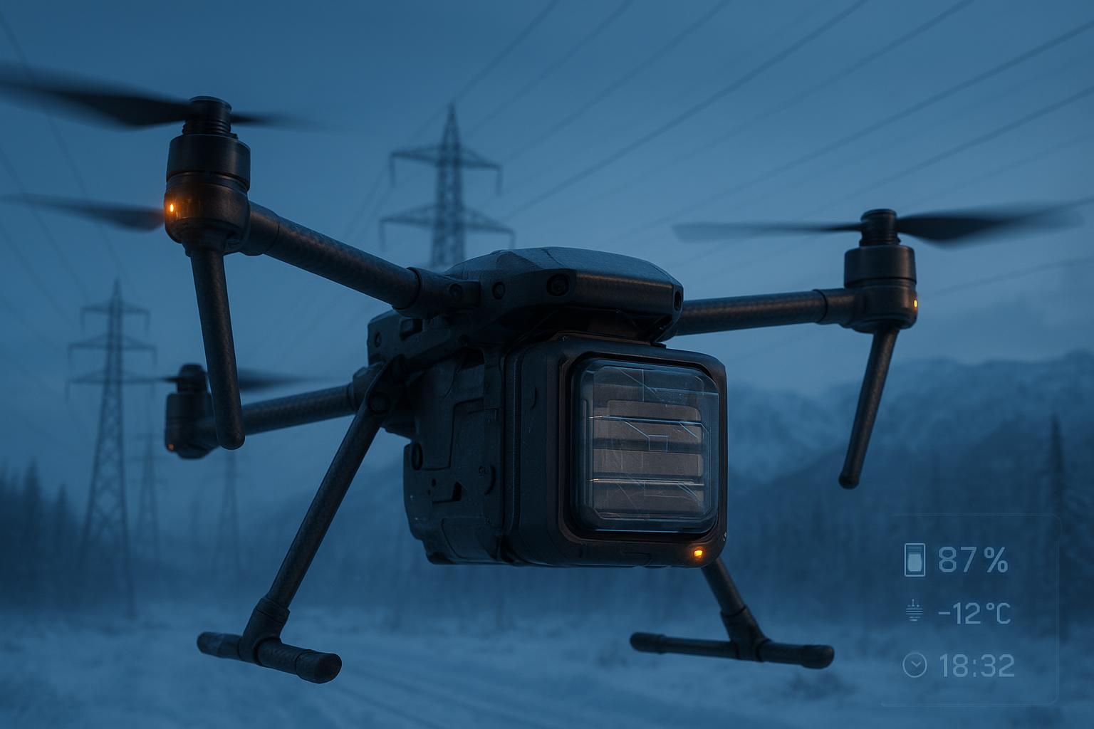
No ROI model is complete without a Weather Adjustment Factor. In cold climates, usable Wh can drop by 15–35%, requiring pre-heat cycles that increase pad time. For your specific region, apply a 0.65–0.85× multiplier to usable Wh and adjust your sorties-per-hour accordingly.
For fleets operating lighter 6S (22.2 V) platforms, the Wh and currents scale proportionally, and the ROI trajectory remains similar: Swapping wins on volume and asset longevity, while fast-charging is reserved for low-utilization sites.
While managed swap-hub protocols preserve cell integrity, aggressive fast-charging triggers specific degradation mechanisms that are well-documented in global energy research. According to NREL’s Extreme Fast Charge (XFC) program, high-rate charging accelerates chemo-mechanical cathode cracking and lithium plating—two primary drivers of premature capacity fade and resistance growth. For operators conducting deep technical due diligence, we recommend reviewing NREL’s modeling notes on cathode particle cracking to validate the conservative cycle-life inputs used in this ROI model.
Safety and Compliance: A Supplier Audit Checklist
In scaling swap-hub operations, safety documentation is a regulatory and insurance mandate. Use this matrix to audit your supplier’s technical packet before committing CAPEX.
Standard/Body | What it governs | What to request in an audit packet |
|---|---|---|
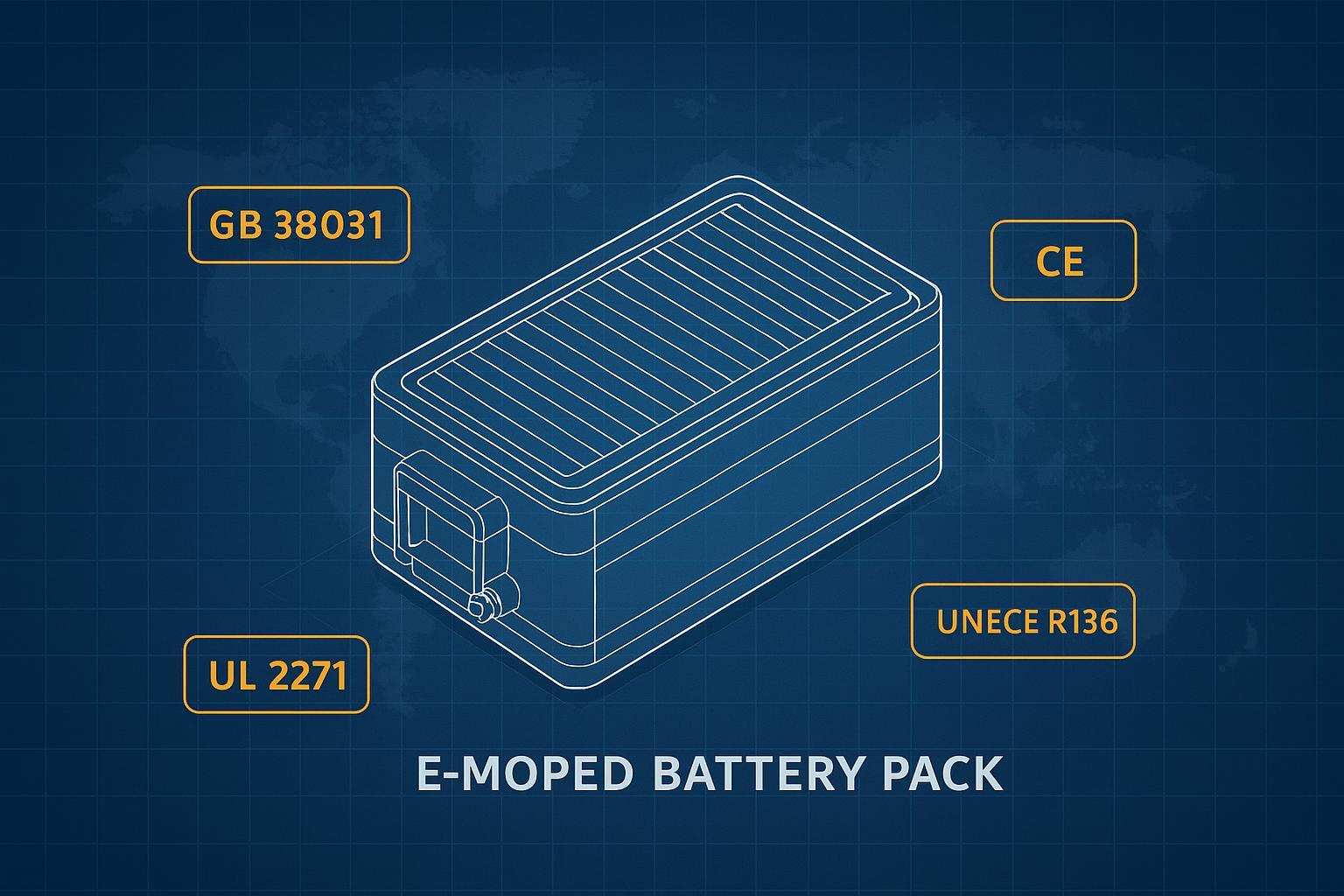
UN 38.3 (UNECE Manual of Tests and Criteria) | Transport safety (T1–T8) | Per-model UN 38.3 Test Summary (PHMSA-aligned where applicable) + report references + revision used (e.g., Rev. 8) |
IEC 62133‑2 | Cell/pack safety design & abuse testing | CB Test Report for the specific pack family (with lab name, report number, and scope notes for variants) |
UL 3030 | UAS electrical system safety (up to ~100 V DC) | Evidence of evaluation/listing for the UAS system or relevant sub-assemblies where applicable + scope limitations |
IATA Lithium Battery Guidance / DGR | Air transport packaging & SoC constraints | Current-year guidance alignment + packing instruction used (PI/S.P.) + shipper SOP for your scenarios |
NFPA 855 (infrastructure context) | Storage/charging site fire safety | Site SOPs for storage/charging + detection/suppression/ventilation design notes aligned to local code adoption |
Practical note: In a supplier audit, the highest value is usually the report identifiers and scope (which exact model/family is covered), not a generic statement that “we comply.”
Engineering audit: swap connector integrity
Cells fail slowly; swap interfaces often fail abruptly. Treat the connector as a safety-critical subsystem and request:
Durability (EIA-364-09): cycle-test evidence at your insertion rate (targeting 5,000–10,000 cycles for last-mile cadence).
Contact resistance (EIA-364-23): LLCR baseline + drift after cycle/environment testing.
Temperature rise vs. current: curve at the peak current you see during takeoff/hover.
Vibration discontinuity: criteria that demonstrate no power interruptions under flight vibration profiles.
If you’re standardizing on a blind-mate ecosystem (e.g., AS150U-class interfaces), ask for test artifacts on the full mating system (connector + mounting compliance + funnel geometry), not the connector in isolation.
Action checklist: what to send in your RFI
Compliance documents (legal/regulatory): UN 38.3 Test Summary, IEC 62133-2 CB report, and any UL 3030 evidence relevant to your platform.
Performance & reliability (engineering): connector cycle test + LLCR drift + temp-rise curve + vibration discontinuity criteria.
Traceability: lot/batch traceability, change-control process, and what triggers a new report vs. an extension.
Operations: storage/charging SOPs and emergency response procedures for your hub layout.
The Urban Lunch-Rush Stress Test
Technical specifications are best validated during the “Lunch-Rush”—a 3-hour peak window where fleet availability directly dictates revenue density.
1. The Operational Scenario
Environment: Dense urban logistics hub; high-frequency turnaround.
Mission Profile: 2.2 kg payloads; back-to-back 5 km sorties; aggressive 3 m/s vertical climbs.
The Technical Challenge: Rapid successions of high-current draws (up to 4.5C during takeoff). In these phases, Voltage Sag is the primary enemy. If unmanaged, sagging voltage triggers premature “Low Battery” failsafes, forcing expensive mission aborts.
2. The “Zero-Abort” Protocol
To maintain Service Level Agreements (SLAs), we implement a three-tier battery management policy supported by Herewin’s cloud-linked BMS:
Predictive DCIR Screening: Our system flags any pack exhibiting a +25% rise in DCIR (Direct Current Internal Resistance) relative to the fleet median. These packs are automatically re-binned for lower-stress utility missions.
Thermal-Aware Dispatch: Using the 1 Hz sampling cadence, the dispatcher only assigns high-cadence routes to packs that have stabilized between 25°C and 45°C, avoiding the accelerated degradation seen in extreme temperature bands.
Imbalance Enforcement: Any pack with a cell-to-cell voltage delta >50 mV (at rest) is locked for corrective balancing to prevent “weak cell” failure during peak climb.
3. Modeled Results: Throughput as a Competitive Edge
By shifting from on-pad charging to a Quick-Swap workflow (60–90s cadence), a 3-drone hub configuration achieves:
Peak Throughput: Sustained delivery of 80–110 sorties within the 3-hour window, compared to only 36 sorties under a fast-charge regime.
Reliability: IR-screening and precision SOC monitoring (±3%) reduce voltage-sag-induced aborts from 1.2% to 0.3%.
Thermal Integrity: Because batteries are slow-charged (0.5C) inside the swap station, they enter the drone with an ideal chemical state, bypassing the “Cathode Cracking” fatigue identified by NREL as the primary killer of fast-charged cells.
Disclaimer: These projections are based on standardized modeling and Herewin’s 2026 performance baselines. Actual ROI and flight reliability may vary depending on local weather, payload types, and fleet maintenance protocols.
Next Steps: Strategic Scaling & Integration
As drone logistics transition to 24/7 unattended operations, the focus shifts from hardware reliability to data-driven fleet intelligence. The precision telemetry established in BMS acts as the foundation for AI-optimized energy management, enabling operators to predict battery fatigue before it triggers a mission abort.
By prioritizing mechanical compliance (AS150U) and intelligent swap-hub protocols today, you are preparing your fleet for future AI-driven load flattening. This will allow your stations to synchronize charging cycles with off-peak energy rates, further driving down the Total Cost per Delivery (TCPD) modeled in this guide.
Quick-swap technology removes the fundamental bottleneck of drone logistics. Utilize the benchmarks established here to scale your operations with confidence.