







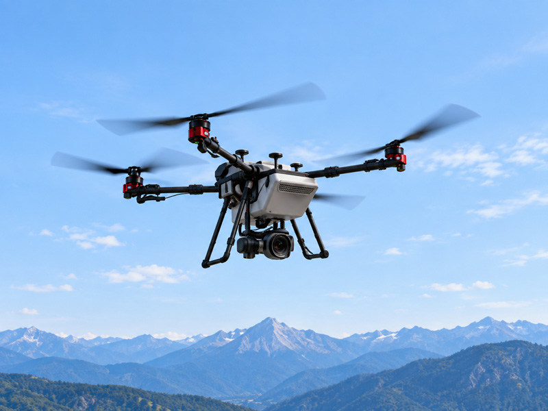



Specification compliance and mission success are not the same thing. A pack can clear every electrical and mechanical requirement on paper and still fall short on the aircraft, because a datasheet describes a component while a mission describes a demand. Custom UAV battery pack design exists to close that gap, and it does so in one direction: aircraft requirement, then battery specification, then pack architecture, integration, validation, and mass production.
This guide follows that spine end to end, including the sample-to-production handoff most resources skip. It is written for R&D engineers, product managers, and system developers, and it closes with a requirements template you can hand to any supplier.
Why Custom UAV Battery Pack Design Starts With the Aircraft
That gap appears whenever a pack is chosen from a catalogue first and matched to the aircraft second. The reliable order runs the other way: the specification is derived from the aircraft and the mission, then the cells, architecture and interfaces follow.
In practice, the derivation is a chain rather than a single calculation. Average power comes from segmenting hover, climb, cruise, transition and landing instead of one global figure, and the specification is built backward from payload, MTOW, target endurance, ambient temperature, reserve requirement and the propulsion platform constraints. Watt-hours follow from average power multiplied by endurance time, amp-hours from watt-hours divided by nominal voltage, and the C-rate from sustained and peak current divided by capacity.
Aircraft requirement → battery specification → pack architecture → integration → validation → mass production.
Published weight or category bands can provide an initial reference, but they should not replace requirements derived from the actual propulsion system and mission profile.
Most readers arrive in one of four states: a new development with no pack defined, a replacement on an existing platform, a standard pack that falls short, or a design moving from sample to mass production.
What a Custom UAV Battery Pack Specification Must Contain
A UAV battery pack specification is not a parameter list. It is a set of derived, internally consistent requirements in which every number traces back to a mission profile, an airframe limit, or a certification scope.
The derivation runs in one direction: aircraft first, battery second. What follows is the mapping that direction produces.
Aircraft requirement | Battery parameter it produces |
|---|---|
Operating voltage band the ESC and avionics accept | Voltage window, series cell count, cutoff threshold |
Endurance target at a stated payload and cruise speed | Usable energy, not nameplate capacity |
Climb, hover and gust-correction loads | Continuous and peak current, C-rate headroom |
Airframe mass budget and balance point | Pack mass and centre-of-gravity envelope |
Harness and bay constraints | Connector class, current rating, mating cycle life |
Flight controller and telemetry stack | BMS interface, protocol, data fields exposed |
Operating environment and duty cycle | Thermal path, ambient limits, cycle-life target |
Route to market and transport mode | Certification scope, test evidence required |
Voltage window and usable energy
Common lithium-ion and Li-Po cells reach about 4.2 V per cell at full charge, while the minimum operating voltage is chemistry-, cell-, load- and system-dependent; the cutoff is a design choice rather than a universal constant (Industrial UAV Battery Specs: Beyond mAh and C-Rating).
Nominal series sums follow: 3S lands at 11.1 V nominal and 12.6 V full, 4S at 14.8 V and 16.8 V, 6S at 22.2 V and 25.2 V.
Usable energy is a different quantity from nameplate energy. Voltage sag under load follows V terminal ≈ V OCV − I·R, so a pack can reach ESC or BMS cutoff before its nominal watt-hours are delivered. Usable capacity is therefore current- and resistance-dependent, not a static Wh figure. A larger-capacity pack with higher internal resistance can sag further at the same hover current, reach cutoff earlier, and deliver fewer usable watt-hours than a smaller, lower-resistance pack with healthier C-rate margin — which is why a higher mAh figure does not automatically mean more flight time.
Current, mass and interface parameters
Continuous and peak current ratings belong on separate lines, because hover, climb and gust correction draw at different levels for different durations. C-rate headroom is the margin between the pack’s specified continuous and peak capability and the aircraft’s actual current demand under the defined duty cycle and temperature conditions, and it decides whether a pack that passes a bench test survives a hot day at altitude.
Mass and centre of gravity belong in the specification, not the mechanical drawing alone. A pack that meets every electrical requirement but shifts the balance point outside the flight controller’s trim authority is not a valid design.
Connector class, BMS interface and thermal limits are interface parameters. They constrain what the rest of the aircraft can be, so they are fixed early rather than selected at the end.
If a standard pack already meets the required voltage window, usable energy, current demand, mass and envelope, connector, BMS interface, environmental conditions and certification scope, custom development may not be necessary. Custom design becomes relevant when one or more of those constraints cannot be met simultaneously by an existing configuration.
Translating Mission Profile Into Electrical Requirements
Average power is estimated by segmenting hover, climb, cruise, transition and landing, not from one global figure. Each phase has a different duration and load, so the energy total is a sum of phase contributions, and the current total is set by the worst phase rather than the average.
Work the derivation in this order:
Energy per phase. For each phase, multiply its power draw by its duration, then sum: E total = Σ (P phase × t phase). Add a reserve margin for wind, payload variance and go-around.
Continuous current. Continuous current comes from the sustained mission load defined by the duty cycle. I cont = P sustained ÷ V nominal.
Peak current. Peak current comes from takeoff, climb and gust recovery. Size the pack, wiring and protection to this value, not to I cont.
Usable energy. Apply the end-of-life convention: many teams define end of life at 80% state of health, so plan capacity against the degraded pack, not the fresh one.
Example assumption: a 12S pack at 44.4 V nominal, 8 kW hover, 14 kW peak climb, 22-minute mission. I cont ≈ 180 A, I peak ≈ 315 A, E mission ≈ 3.0 kWh before reserve. Illustrative example only; actual sizing requires measured aircraft power data.
Cell-level figures do not transfer directly. Li-ion and Li-Po cells typically sit in the 100-265 Wh/kg band, though cell-level energy density is only one input. At pack level, housing, interconnects, BMS, protection and thermal design reduce the energy density available to the aircraft, so the relevant figure is the usable pack-level energy per kilogram, not the cell number on a datasheet.
Charge rate should be defined against the fleet’s turnaround requirement, pack temperature and charger capability rather than treated as a headline performance figure.
The current and energy figures produced here set the boundaries for cell and architecture selection.
Cell Selection and Pack Architecture Decisions
Cell selection in custom UAV battery pack design begins with the duty cycle, not the datasheet headline. Series count fixes the voltage window your propulsion system sees; parallel count determines how capacity and current demand are distributed across the parallel groups. The two are not independent, because adding parallel strings to raise capacity also raises pack mass, which raises the power the aircraft needs in the first place.
Chemistry is where the trade-off becomes unavoidable. A 2020 review of energy sources for UAVs reports that Li-Po and Li-ion remain the most common drone batteries, while alternatives such as Li-air and Li-SOCl₂ are still not widely available and cost far more (PMC7672221). Chemistry involves a trade-off between energy density, power capability, cycle life, thermal behaviour and cost, and a chemistry that favours endurance costs you peak power while one that favours peak power costs you cycle life. Pick against the mission profile, not against the highest number on a spec sheet.
Once the topology is fixed, cell format, tabbing, busbar cross-section, and compression control follow from it. Each of those choices moves mass and centre of gravity, so treat them as airframe decisions, not battery-housekeeping.
BMS Integration as a System Interface
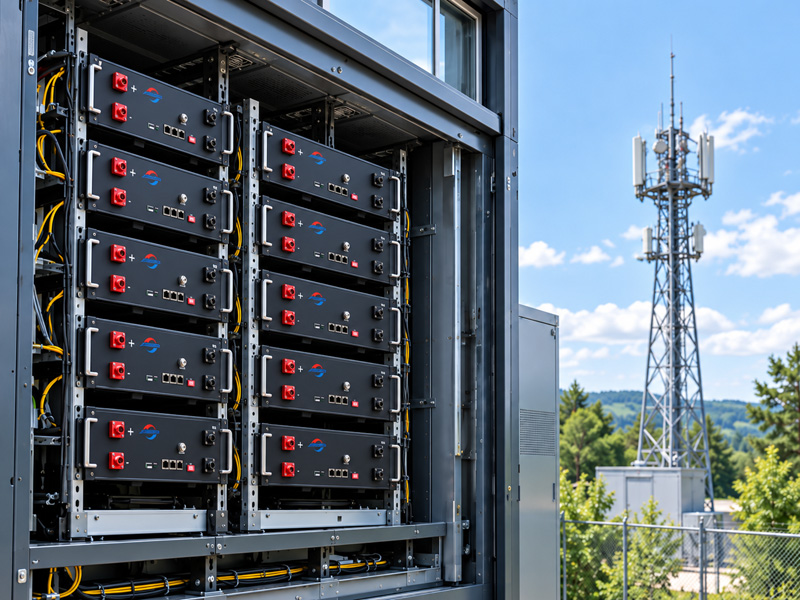
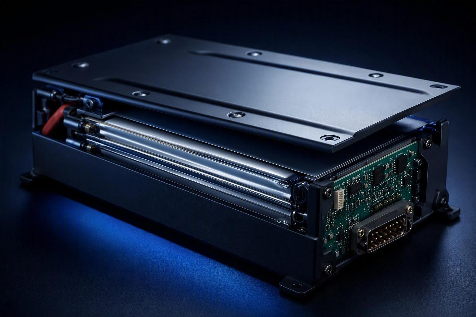
UAV battery BMS integration is an interface decision, not a protection feature bolted inside the pack. Depending on the battery architecture, the BMS or battery-monitoring system may expose pack voltage, current, temperature, SOC, SOH and fault information to the aircraft control system, which then surfaces it to flight-control and ground-station software. Secondary paths may carry the same data to a smart charger for pack ID and charge permission, or through a gateway to a companion computer.
The protocol you choose sets the integration work. CAN-based protocols such as DroneCAN are commonly used where the battery must integrate with an aircraft data bus, offering broadcast messaging, defined message IDs, termination and shielding, while SMBus and I²C are polled single-master exchanges better suited to short-distance or charger-oriented use.
Protocol | Topology | Typical use | Integration cost |
|---|---|---|---|
CAN / DroneCAN | Broadcast, multi-node | Airframe backbone to flight controller | Low if the stack already subscribes to battery messages |
SMBus / I²C | Polled, single-master | Smart-battery registers, charger handshake | Moderate; polling loop and timing must be tuned |
UART | Point-to-point serial | Proprietary or MAVLink-compatible links | Moderate to high; framing often vendor-specific |
Flight stacks such as PX4 can subscribe to DroneCAN battery messages rather than polling them, which changes how thresholds and failsafe timers are configured. When the protocol does not match, the symptom is rarely a battery failure. It shows up as integration engineering time: field mapping, unit scaling, threshold tuning and gateway work that procurement timelines seldom plan for. Settle the protocol before the connector and envelope freeze, so the interface can be validated with the rest of the pack rather than patched in afterward.
Connectors, Mechanical Envelope and Thermal Path
Connector selection is where a custom UAV battery pack design stops being a spreadsheet and starts constraining the airframe. The connector’s voltage and current rating, its contact resistance, its retention under vibration and its keying all feed back into the mechanical envelope and thermal path, so the decision belongs in the design review, not in the bill of materials.
Rating and derating. Size the connector using the manufacturer’s current-rating and derating data under the expected temperature and installation conditions, not on its headline number. Contact resistance matters because it adds directly to voltage sag, and it should be measured on the sample rather than assumed.
Envelope and retention. Mounting, crash-load path and serviceability set the envelope, and any late mass change invalidates the CG budget the airframe was balanced around. Ask for the retention test method, mating-cycle count and ingress rating in writing.
Thermal path. Cell-to-ambient resistance, not cell temperature alone, determines whether the pack survives a climb. Continuous and peak thermal duty differ, so temperature rise rate belongs in validation as a measurement, not a design assumption.
Validation: Proving the Pack Before Production
UAV battery pack validation proves the pack meets its specification across the whole mission envelope and temperature range, not that one unit survived one test. Start by writing the acceptance criteria down, then test against them.
Cell acceptance is the first gate. Incoming-cell acceptance criteria for capacity, resistance, voltage consistency and self-discharge should be defined and the thresholds agreed before production, not after units fail in the field. A published baseline for heavy-lift builds shows the kind of screening worth demanding, but treat any such figure as a working baseline rather than a UN or IEC requirement.
Design validation then stresses the assembled pack: thermal shock across the stated temperature limits and a short-circuit isolation target, following a design-FMEA review that scores mid-air power cutoff at maximum severity. Production quality control then applies the agreed screening and end-of-line test plan to each pack, or according to the defined sampling plan.
Flight logs close the loop. Check peak current, minimum pack voltage during step climbs, temperature rise rate and per-cell divergence against the C-rate band you designed for, and treat any margin shortfall as a design change rather than a test note. The output of this stage is a pack whose behaviour is understood across the whole envelope, so the next step is to freeze it and prove that a production line can repeat it.
Certification as a Design Constraint
Certification scope in custom UAV battery pack design is set by the pack configuration, so it has to be decided before the design freezes rather than after. UN 38.3 is a transport-design testing requirement whose applicable test scope depends on the cell, battery or battery-assembly configuration, and on factors such as the number of cells, Watt-hour rating and protection architecture, so it cannot be assumed to carry over from the cell to the finished pack. Treat it as a design input, not a shipping form.
The other standards sit at different levels, and mixing them up is where programs lose time. IEC 62133-2 covers portable sealed secondary lithium cells and batteries under intended use and reasonably foreseeable misuse, though it should not be assumed to apply to every UAV pack by default. UL 1642 is commonly associated with lithium battery cells, while UL 2054 addresses certain household and commercial battery applications; neither should be assumed to be the default certification route for every UAV battery, because the applicable standard depends on the product, market and end-use requirements. CE is a market-access marking that depends on the applicable EU directives and the technical file, not on a single battery standard. Some aerospace or aviation programs may also impose environmental or equipment-level testing requirements, depending on the aircraft and market.
The applicable UN 38.3 test sequence and sample configuration depend on the battery design and its relationship to any tested component cells or batteries. For context, PHMSA’s reading of the UN Manual is that a lithium-ion battery assembly rated at or below 6,200 Wh must be built from batteries that have passed the applicable tests and must then itself undergo additional tests (T.3, T.4, T.5, and T.7 for a rechargeable assembly) — a scope question, not a fixed sample count (PHMSA Interpretation 24-0019, 2024). Confirm the required test scope and sample count with the accredited test laboratory before freezing the production configuration, rather than assuming a fixed sample quantity.
The certification-scope decision point sits before design freeze, not after. A change that affects safety behaviour — a different cell, a revised protection circuit, a new enclosure — can place the pack outside the scope of its existing test report, and the earlier test campaign then no longer covers the product you intend to ship.
With the scope settled, the pack can be frozen and handed to production, where a validated design faces a second kind of test: not against its specification, but against the ability of a production line to reproduce it.
From Sample to Mass Production
Custom UAV battery pack mass production is where a design stops being a prototype and starts being a distribution. A sample is one build, measured once, on the day it was made. A production run is thousands of cells, each slightly different, assembled into packs that all have to behave the same way in month three as they did in week one.
That shift is the whole problem. In production, pack performance is set by the tails of the cell distribution rather than by the average cell (Prototype UAV Batteries: Why Production Scale Fails). Usable energy in a series string is capped by the lowest-capacity cell or the weakest parallel group, so a pack is only as good as its worst group. Resistance spread is often more damaging than capacity spread, because voltage sag scales with current times resistance and heat scales with current squared times resistance. A prototype is judged on its day-one behaviour, which means production failures may only surface after repeated cycling and fleet deployment.
Two controls close that gap. The first is design freeze and configuration control: once the pack is validated, cell part number, BMS firmware, connector, and mechanical envelope are locked, and any change re-enters validation rather than shipping quietly. The second is the pilot batch, which tests repeatability, not capacity. You are checking whether run-to-run spread of key parameters stays inside the specification limit, batch after batch, before committing to volume.
Incoming cell screening is what makes both controls real. Cells are accepted or rejected against spread criteria before they enter a pack, so the tails of the distribution are removed at the gate instead of discovered in the field. Validation defines what the pack must do; screening and configuration control are what keep a production fleet doing it.
A typical ODM/OEM engagement runs through requirement gathering, prototyping, sample production, feedback and iteration, then mass production with inspection stages per pack. Whatever supplier you use, the schedule should be tied to the frozen configuration rather than to a headline lead time, so ask for those dates in writing against your specific build.
What to demand from any supplier before you release volume: the frozen configuration list, the pilot-batch spread data against your limits, the incoming screening criteria and the sampling plan behind them, and a written change-control process. If a supplier cannot show run-to-run data, you are buying the prototype, not the production pack.
Custom UAV Battery Pack Project Requirements Template
The specification sections above produce a derived design. This template is what you hand to a supplier to start that derivation, and it is the same set of fields any competent supplier needs before quoting. Fill in what applies and mark the rest as an open question.
Requirement | Information to provide |
|---|---|
Aircraft platform | Model and configuration |
Application | Agriculture, inspection, delivery, heavy-lift, or other |
Payload | Target payload mass |
Target flight time | Minutes, at a stated payload and speed |
Voltage | Operating voltage range the ESC and avionics accept |
Continuous current | Amps |
Peak current | Amps and duration |
Required usable energy | Watt-hours, after reserve and end-of-life margin |
Battery mass limit | Kilograms |
Dimensions | Length × width × height |
Centre of gravity | Required position or envelope |
Connector | Type and location |
BMS | CAN / DroneCAN / SMBus / UART / other |
Required data | Voltage, current, SOC, SOH, temperature, fault fields |
Pengisian daya | Charger type and maximum charge rate |
Environment | Temperature, humidity, dust and vibration exposure |
Housing | Mounting, sealing and ingress protection requirements |
Sertifikasi | Target market and required standards |
Sample quantity | Units needed for evaluation |
Validation | Required test conditions |
Target production | Units per month or year |
The more of these fields you can provide before the first design review, the fewer assumptions the supplier has to make for you. An incomplete template is still useful, because the gaps tell both parties where the risk sits.
Pertanyaan yang Sering Diajukan
How long does custom UAV battery pack design take from brief to mass production?
Plan on weeks, not days, but the schedule is driven by iteration count rather than by manufacturing. Sample build and mass production each take their own lead time, and those dates should be quoted against your frozen configuration rather than taken from a general figure. The variable is how many sample rounds your acceptance tests force: a pack that passes vibration and thermal trials on the first build compresses the program, while a chemistry or connector change after the first flight test restarts validation. Iteration count, not manufacturing throughput, is what usually sets the calendar, so your own test plan is the real schedule driver.
Is a custom UAV battery pack more expensive than a standard one, and when is standard genuinely sufficient?
Custom costs more per unit at low volume, and a standard pack is usually sufficient when your airframe already fits a catalogue pack’s voltage, envelope and connector. A custom pack becomes justified when the mission profile cannot be met by an off-the-shelf configuration: a peak current the standard pack’s continuous rating cannot hold, a mechanical envelope no catalogue size fits, or a BMS protocol your flight controller does not speak. The cost question is therefore also a program-risk question, because a standard pack that forces an airframe redesign usually costs more than the custom pack would have.
What information does a UAV battery supplier need to start a custom design?
At minimum: the aircraft platform and application, payload, target flight time, the voltage range the ESC and avionics accept, continuous and peak current, required usable energy, the mass and dimension envelope, the centre-of-gravity position, the connector, the BMS protocol and required data fields, charging limits, the environment, housing requirements, the certification target and the intended production volume. The Project Requirements Template above captures all of them, and the more fields you fill in before the first design review, the fewer assumptions the supplier has to make on your behalf.
When should we choose a custom pack instead of modifying the aircraft?
Modify the aircraft first when the change is small and reversible, such as relocating a small amount of ballast or adjusting a mounting bracket, because the standard pack already passes its certification and its supply chain exists. A custom pack becomes the better route when the requirement itself is the constraint: the mission needs more usable energy or peak current than a catalogue pack can provide at the envelope and mass you have, no standard voltage or connector configuration matches your propulsion and avionics, or the BMS protocol your flight controller depends on has no off-the-shelf equivalent. Certification scope is often what tips the decision, because an airframe change that alters pack configuration reopens validation, while a custom pack is designed into that scope from the start.
Submitting Project Requirements
Custom UAV battery pack design works when the specification is derived from the aircraft rather than selected from a catalogue. That discipline is what makes a pack designable, verifiable and producible: the mission profile sets the electrical requirement, the cells and architecture follow from it, and every interface you define becomes something a supplier can be held to at acceptance.
The sequence is what holds. Requirements define the design. Validation decides whether the design is ready. Configuration control decides whether production can reproduce it. Every parameter in between, from cell format to BMS protocol support, keeps changing, and a copied parameter sheet will not survive those changes; the discipline of deriving, proving and freezing will.
If you have an aircraft requirement and no frozen pack specification yet, the next step is a technical conversation, not a purchase order. Submit Project Requirements with your mission profile, envelope constraints and interface expectations, and the derivation can start from the airframe you actually fly.

 Bahasa Indonesia
  English
  Español
  한국어
한국어  Deutsch
  Français
  日本語
日本語  Русский
  ไทย
ไทย  العربية
  Português do Brasil
  Italiano
  Nederlands