


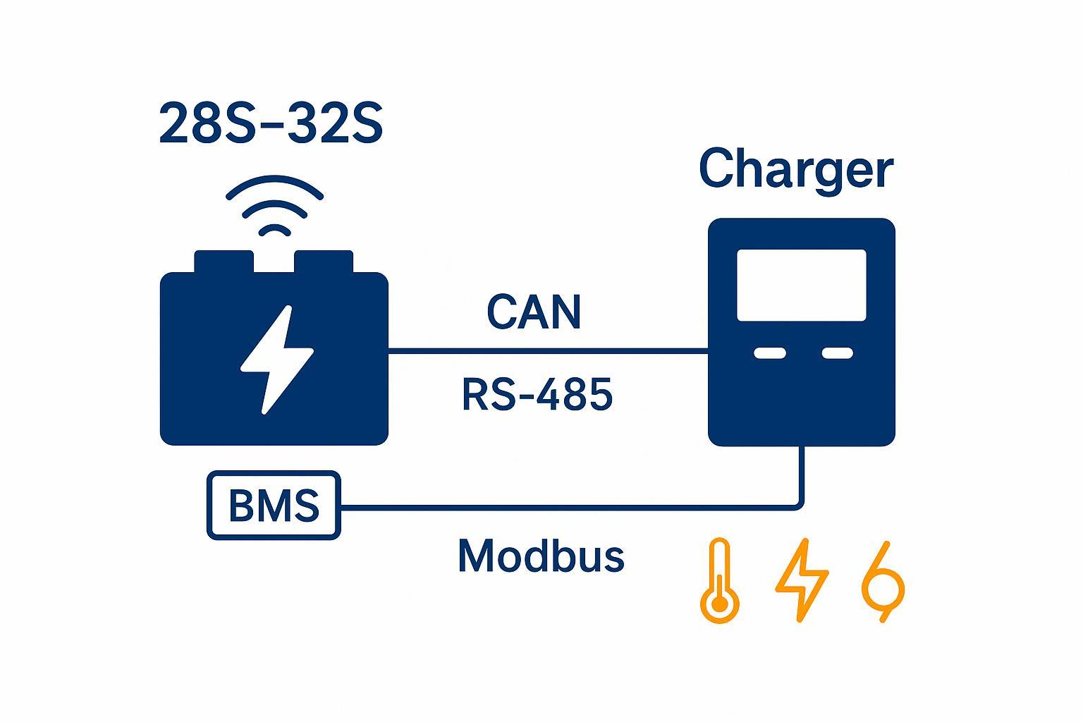
If you’re charging a 6S LiPo on a bench charger, you can often “get away with” static settings and a careful operator. That model breaks at 28S–32S.
At 28S–32S, charging is not a human task. It’s a control problem: a multi-sensor, multi-limit system where the battery management system (BMS) measures what’s happening inside the pack and the charger must act on those measurements—continuously. This is why BMS charger communication isn’t a nice-to-have in industrial UAV operations. It’s the mechanism that makes charging deterministic, scalable, and defensible during audits.
For engineering teams evaluating a high voltage lithium battery charging system, the core question is simple: can the charger prove it will stay inside the BMS-approved envelope when conditions change (temperature, imbalance, aging, comms loss)?
Below is the system-level logic for 28S 32S UAV battery charging, the control parameters that matter, and the failure modes you must design out.
Why 28S–32S charging becomes a system-level challenge
Who actually uses 28S–32S UAV battery systems
28S–32S platforms typically appear when the UAV is treated like industrial equipment rather than a hobby vehicle. The typical buyers and integrators are:
UAV OEM manufacturers shipping heavy-duty airframes with defined charging infrastructure
Industrial UAV system integrators and fleet energy system engineers responsible for 28S–32S high-voltage charging infrastructure
Fleet operators running repeatable cycles (agriculture, inspection, mapping, public safety)
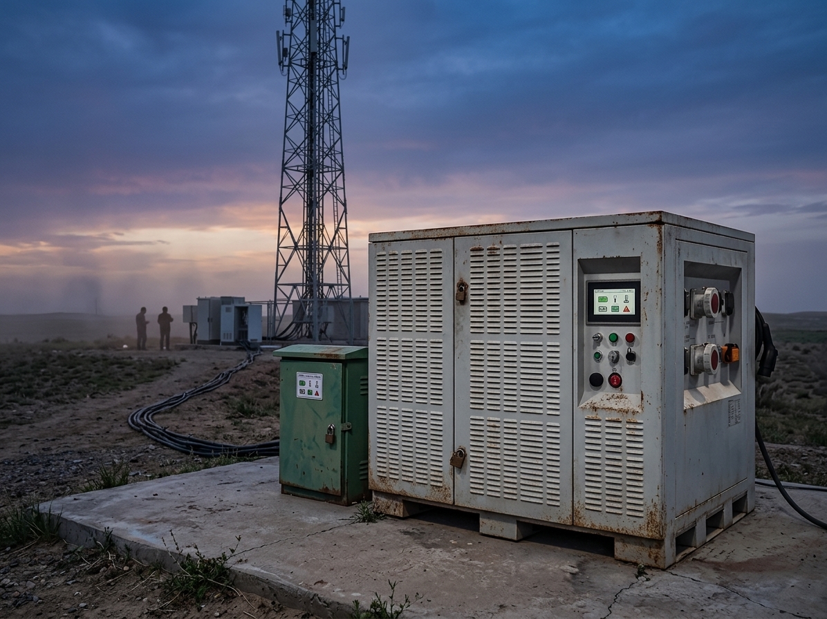
In these contexts, the battery isn’t “a consumable.” It’s an uptime and liability component—especially for maintenance engineers responsible for field charging operations and depot workflows.
Why high-voltage charging can’t rely on manual operation
In industrial charging bays and field depots, three realities drive the need for closed-loop control:
Multi-battery throughput: you’re charging many packs per shift; a “small” setup mistake becomes repeatable damage.
Field variability: temperature, line power quality, generator use, and turnaround pressure introduce uncontrolled conditions.
Safety and compliance exposure: incidents are investigated; you need logs, limit enforcement, and a defensible process.
Static setpoints assume the world stays constant. Fleet charging doesn’t.
Architecture of 28S–32S UAV battery systems
What defines a 28S–32S battery system
A “28S–32S” pack is defined by series count (S): the number of cells in series determines the voltage window and the charging ceiling.
Two common families matter here:
Li-ion / LiPo (typical max cell charge voltage ≈ 4.2V per cell for many cells)
LiFePO4 (LFP) (typical full-charge per cell around 3.65V per cell)
To see why the system changes, do the math.
For Li-ion/LiPo, Adafruit notes that the maximum voltage of the cell is typically 4.2V in its guide to Voltages | Li-Ion & LiPoly Batteries.
Example assumption (Li-ion/LiPo @ 4.2V/cell):
28S full-charge ceiling ≈ 28 × 4.2V = 117.6V
32S full-charge ceiling ≈ 32 × 4.2V = 134.4V
Example assumption (LiFePO4 @ 3.65V/cell):
28S full-charge ceiling ≈ 28 × 3.65V = 102.2V
32S full-charge ceiling ≈ 32 × 3.65V = 116.8V
At 28S–32S, the “same charger” is rarely safe across chemistries or even across cell variants. The charge ceiling is chemistry- and cell-spec-dependent, not just S-count dependent.
LiPo vs LiFePO4 selection (engineering lens)
Choose LiPo when you’re optimizing energy and power density under strict takeoff-weight constraints, and you can enforce tight charging/thermal SOPs.
Choose LiFePO4 when you’re optimizing operational safety margin, thermal tolerance, and lifecycle stability, and you can accept the energy-density trade.
The control logic is mandatory for both—but the margin for error is often smaller with high-energy, high-C architectures.
Role of the BMS in an industrial battery system
In industrial fleets, the BMS isn’t “an accessory.” It’s the control layer that turns a high-energy pack into a managed asset.
At minimum, a pack-level BMS provides:
Safety enforcement: cell/pack overvoltage, undervoltage, overcurrent, overtemperature protections
SOC/SOH observability: readings that drive charging phases, dispatch decisions, and maintenance planning
Balancing control: limiting cell divergence so one cell doesn’t become the failure trigger for the entire pack
If you want a deeper, Herewin-based explainer on why high-series packs benefit from stricter BMS discipline, you can use this technical reference: Herewin — why 24S–32S packs need a smart BMS.
Role of the charger in high-voltage systems
In a 28S–32S system, the charger should be treated as an execution controller (actuator), not a “dumb power supply.”
Its job is to:
Deliver CC/CV charging safely
Follow the charge envelope (voltage/current/temperature limits) defined by the BMS
Fail safe when control inputs are missing, inconsistent, or unsafe
Why BMS charger communication is mandatory
What happens without communication
Without BMS-to-charger communication, you are effectively charging blind. The charger operates on static assumptions while the pack behavior changes with:
cell-to-cell divergence
temperature gradients
aging (SOH shift)
sensor drift and connector resistance
In a 32S system, a single incorrect assumption scales across many cells.
Three predictable outcomes follow:
Voltage mismatch risk: the charger can’t reliably prevent a single cell from reaching its limit first.
Thermal accumulation: current that was safe at 20°C becomes unsafe at 35°C with restricted cooling.
Incomplete cycles: early cutoffs, repeated partial charges, or nuisance trips degrade usable capacity and predictability.
What communication actually enables
BMS charger communication creates a closed loop. The BMS measures; the charger acts.
At a practical level, communication enables:
Dynamic charging curve control: the charger can adapt current and voltage targets over time.
Synchronized safety thresholds: the charger knows the BMS limits (and the BMS knows what the charger is doing).
Adaptive power output: throttling when cells are cold/hot, unbalanced, or aged.
This is the difference between “charging works in the lab” and “charging works every day, across a fleet.”
Charging control parameters: the technical logic layer
Think of 28S–32S charging as a single controller with multiple inputs. Voltage, current, temperature, and state estimates aren’t separate topics—they’re coupled control signals.
Voltage control
Voltage control is about enforcing the upper voltage ceiling—at both pack and cell level.
Two engineering points matter:
Pack voltage is necessary—but not sufficient.
Cell-level max voltage (defined by the cell spec) is what actually defines overcharge risk.
That’s why the BMS must report cell voltages (or at least the max cell voltage) and the charger must respond.
Current control
Current is where thermal and aging cost shows up.
Charging current defines the C-rate (relative to capacity).
Resistive heating scales with I²R, meaning small current increases can create disproportionate heat.
A control system should treat current as a variable the BMS can throttle based on temperature, imbalance, and SOH.
If you want an internal context link that connects architecture choices to current stress and economics, this Herewin guide discusses S-count, current reduction, and trade-offs: Herewin — S-count, current stress, and TCO.
Temperature window control
Temperature isn’t “nice telemetry.” It’s a charge permission signal.
At low temperatures, charging can trigger lithium plating, a degradation and safety mechanism. ACCURE summarizes the mechanism and risk in its explainer Guide to Lithium Plating in Lithium-Ion Batteries.
At high temperatures, side reactions accelerate, degradation speeds up, and you lose safety margin.
In industrial systems, the correct behavior is:
block charging outside allowed windows
derate current as temperatures approach limits
require stable readings (not a single sample) before re-enabling charge
Battery state inputs: SOC and SOH
SOC and SOH aren’t just dashboard numbers. They are control inputs.
SOC should act as a phase trigger (for example: taper logic, balancing windows, termination).
SOH should modify allowable charge power and expected end conditions, because aged packs behave differently.
Closed-loop charging uses SOC/SOH to make the charge outcome repeatable—not just “full.”
Engineering thresholds layer (practical starting points)
Below are common engineering threshold ranges teams use to translate “control envelope” into actionable limits. Always default to the cell datasheet and your validation tests—these numbers are starting points for system design reviews, not universal specs.
Voltage
Per-cell ceiling is chemistry-dependent (e.g., 4.20V/cell for many Li-ion/LiPo chemistries; 3.65V/cell typical for LFP), then scaled by S-count.
Pack-level CV target should include a manufacturing tolerance and measurement accuracy budget (cell sense + harness + ADC).
Current
Define an operational charge band (commonly 0.5C–1C) and make it deratable by temperature, imbalance, and SOH.
Treat connector and cable I²R heating as part of the limit model, not an afterthought.
Temperature
Implement a strict cutoff window (often around 5–40°C for charging in many Li-ion applications) plus a derating zone as you approach either boundary.
Require stability (e.g., sustained readings for a time window) before re-enabling charge after an out-of-range event.
Cell imbalance thresholds
Define a telemetry-based action ladder such as 0.05V warning and 0.10V shutdown at the cell level (or an equivalent pack-level delta-V rule), then tie those states to charger setpoint reduction and/or charge termination.
This “thresholds layer” is what turns BMS–charger communication from a concept into a repeatable SOP across operators, sites, and seasons.
These thresholds directly map to the 8 system failure modes described in Section 5.
The 8 Most Misconfigured Charging Parameters in 32S UAV Systems (Mapped to Failure Modes)
In industrial UAV systems, most charging failures are not random faults, but predictable outcomes of misaligned control parameters within a high-voltage closed-loop system.
These failure modes often originate from misconfiguration of eight core charging parameters in 32S systems.
Instead of treating these as “operator mistakes,” treat them as system-level failure modes you can design out.
Incorrect series configuration
Failure mode: charger profile doesn’t match S-count or chemistry.
Typical symptom: premature cutoff, never reaching full charge, or overvoltage trips.
Mitigation: enforce a configuration handshake: the charger should not start until it receives (and validates) series count and chemistry profile from the BMS.
Voltage threshold misconfiguration
Failure mode: CV target is wrong, or termination logic is wrong.
Typical symptom: the system “finishes” but SOC is inconsistent; balancing never completes; cells drift.
Mitigation: define charge ceilings from cell spec + verification tests; do not “tune” by raising OVP thresholds.
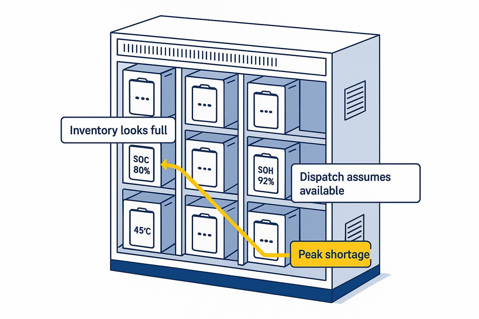
Improper cell balancing strategy
Failure mode: imbalance causes one cell to hit the ceiling early.
Typical symptom: charging stops with low usable capacity; pack looks “full” by max-cell criteria but isn’t full by energy.
Mitigation: require cell-voltage visibility during CV; implement balancing windows; investigate recurring high-cell patterns as a quality signal.
Excess charging current
Failure mode: current setpoint ignores thermal reality and connector resistance.
Typical symptom: packs get hot late in charge; swelling risk increases; SOH drops faster.
Mitigation: make current a closed-loop variable (BMS request/charger enforce), not a fixed knob.
Temperature window violation
Failure mode: charging proceeds while cells are too cold or too hot.
Typical symptom: accelerated aging; inconsistent performance; elevated safety risk.
Mitigation: temperature gating + derating; block charge below cold threshold to reduce plating risk (see ACCURE plating reference).
Incorrect connection sequence
Failure mode: contactor/precharge/enable order is wrong; comms comes up late.
Typical symptom: arcing, nuisance faults, unstable comms, intermittent start failures.
Mitigation: define a deterministic connection state machine: precharge → bus stable → comms heartbeat → charge enable.
Ignored warning/alarm logic
Failure mode: warnings are treated as “noise” and the system continues.
Typical symptom: repeated near-limit behavior becomes normal; the fleet accumulates latent damage.
Mitigation: define alarm classes with mandatory actions; require logs and escalation thresholds (engineering, not operator discretion).
Interrupted charging cycles
Failure mode: partial charges and abrupt stops become the default.
Typical symptom: SOC calibration drifts; balancing never finishes; dispatch becomes unreliable.
Mitigation: design for controlled interruption handling (resume logic, re-handshake, minimum dwell times in CV/balance windows).
Why manual charging fails in industrial UAV operations
Limits of human parameter setting
Manual settings can’t provide:
real-time adaptation
verified feedback control
deterministic fault handling
A person can choose a current. They can’t continuously enforce a safe envelope across 32 series cells as temperature and imbalance evolve.
Risk accumulation in fleet operations
Fleet operations turn small errors into statistical certainty:
A mis-set profile doesn’t hurt one pack—it hurts every pack.
A marginal thermal condition repeats hundreds of times.
“One-off” comms glitches become systematic SOC/SOH drift.
Voltage behavior under load also becomes a reliability gate. If you’re evaluating packs as fleet assets, this internal reference is relevant: Herewin — voltage sag as a fleet reliability criterion.
Engineering recommendation: adaptive charging system design
Why closed-loop charging systems are required
A closed-loop system is required because it gives you three things auditors and fleet operators care about:
determinism (same inputs produce the same outputs)
traceability (you can prove what happened)
bounded risk (faults trigger defined actions)
Recommended architecture for industrial UAV systems
A practical, defensible architecture looks like this:
BMS-driven control envelope
BMS publishes: max charge voltage, max charge current, temperature limits, fault flags, heartbeat.
Charger enforces: current/voltage setpoints and immediate safe-state on invalid inputs.
CAN BMS communication for primary control where robustness matters
Use a linear bus with end termination, minimal stubs, and bitrate appropriate for harness length.
maxon’s guidance on CAN bus topology and termination is a good concrete reference: it calls for two 120Ω terminators (≈60Ω measured across the bus when powered down), stubs under 30 cm, and gives bitrate-vs-length examples.
Modbus battery charger integration over RS-485 for simple, longer, or cost-constrained links (with disciplined wiring)
If you use RS-485, treat star wiring as a design bug.
Texas Instruments explicitly discourages star configurations in The Practical Limits of RS-485 (AN-979), and describes why long stubs create reflection/termination problems.
For a bus/daisy-chain framing, TI’s RS-485 Design Guide (Rev. D) describes a daisy-chain/bus topology with short stubs.
Active balancing and validation hooks
balancing strategy should be visible in telemetry (not a hidden behavior)
commissioning should include fault-injection tests (comms loss, temp sensor fault, high-cell condition)
Treat “BMS–charger communication” as a documented interface contract: message set, update rate, timeout behavior, and safe-state behavior. If it’s not written down, it’s not engineered.
If your team also needs a compliance and documentation path for UAV battery communication, this internal guide is a natural companion: Herewin — industrial drone battery compliance guide.
From battery charging to energy system management
Charging becomes operational infrastructure
At 28S–32S, charging is not “maintenance.” It’s infrastructure—like fueling, dispatch, and safety management.
Your charge system is now part of your uptime equation.
UAV fleets become energy-managed systems
When the BMS and charger communicate, you unlock a management layer:
predictable charge outcomes
controllable degradation
audit-ready logs
standardized SOPs across sites
That’s the shift: from charging batteries to managing an industrial energy system.
Next steps
If you’re designing or retrofitting an industrial 28S–32S charging bay, the fastest way to de-risk the program is to formalize the interface contract early.
Request a BMS–charger interface specification (CAN or Modbus mapping, update rate, timeout behavior)
Ask for an integration checklist (termination, stubs, isolation strategy, fault-injection tests)
Align on SOP + evidence artifacts (logs, parameter versioning, acceptance tests)
For engineering teams designing 28S–32S charging infrastructure, Herewin provides reference architectures for BMS–charger integration, validation workflows, and compliance documentation. If you want to review options, start here: Herewin.