










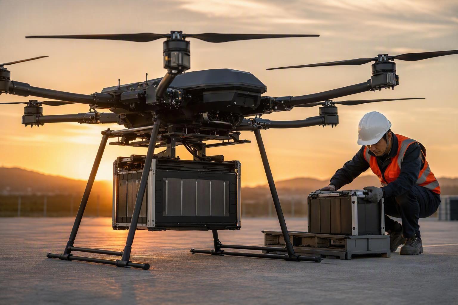
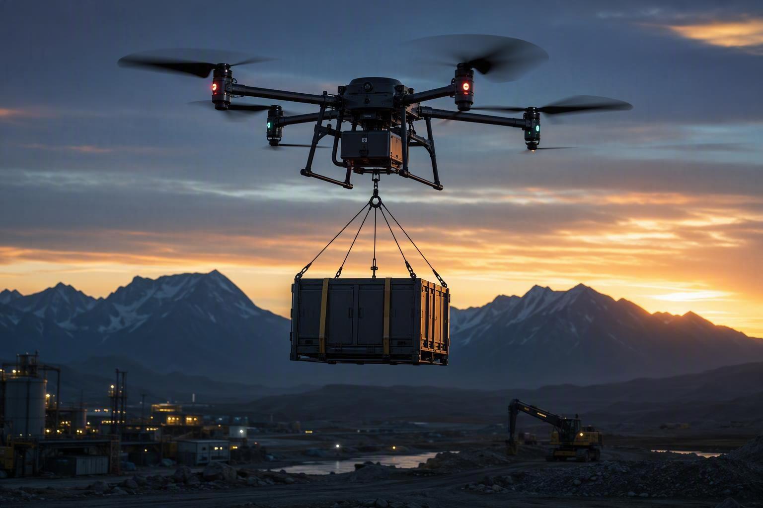
A cargo drone is not designed around a range figure. It is designed around a payload envelope.
That envelope defines the operating limits of the aircraft, including maximum takeoff mass and the combinations of payload, range, and performance the platform is designed to support. Everything the aircraft carries comes out of the same budget: structure, avionics, payload, and battery. The battery is the only item that both consumes that budget and is supposed to pay for it.
Ask how far a cargo drone can fly and the honest answer is a procedure, not a number. Under a given set of assumptions, it flies as far as the usable energy in its pack allows, once that pack has been sized against the payload, the power the mission demands, the conditions on the day, and the reserve the operation requires. Change any one of those and the answer moves.
This guide walks through the six variables in that chain, in the order they constrain each other, and shows how to turn them into a battery requirement you can hand to a supplier.
Why Cargo Drone Range Isn’t a Battery Spec
Published range figures can be measured under payload, weather, temperature, speed, and battery-use conditions that differ from an operator’s actual mission.
The difference is often a matter of test conditions and operating assumptions rather than a direct comparison of the same mission. A manufacturer quoting one range figure at low payload and another at rated payload is describing the same aircraft under different mission conditions.
Three premises need separating before any arithmetic is useful, because they are routinely collapsed into one:
Energy determines how much the battery can store.
พลัง determines whether the aircraft can access that energy under load.
Mass determines how much of that energy is actually useful once the aircraft has to carry the battery itself.
A pack can be strong on the first and weak on the second. It can be strong on both and still lose to a heavier pack on the third. Range is what survives after all three are resolved against a specific mission.
The table below breaks that chain into the six variables this guide works through, and shows whether each one stores energy, consumes it, or removes it from the mission:
Variable | What sets it | Effect on cargo drone range |
|---|---|---|
Usable energy | Pack-level energy density, SOC window, temperature, discharge rate | Sets the energy available for the mission |
Battery mass | Cells, enclosure, BMS, harnessing, thermal hardware | Consumes MTOW and increases power demand |
Payload | Mission requirement | Consumes MTOW and increases power demand |
Power demand | Climb, hover, cruise, wind, maneuvering | Determines how quickly stored energy is consumed |
Flight conditions | Altitude, wind, temperature, precipitation | Changes propulsion and battery performance |
Reserve | Operational and regulatory requirements | Removes energy from planned mission use |
Usable Energy: Cell Data vs Pack Data
Cell vs Pack Energy Density
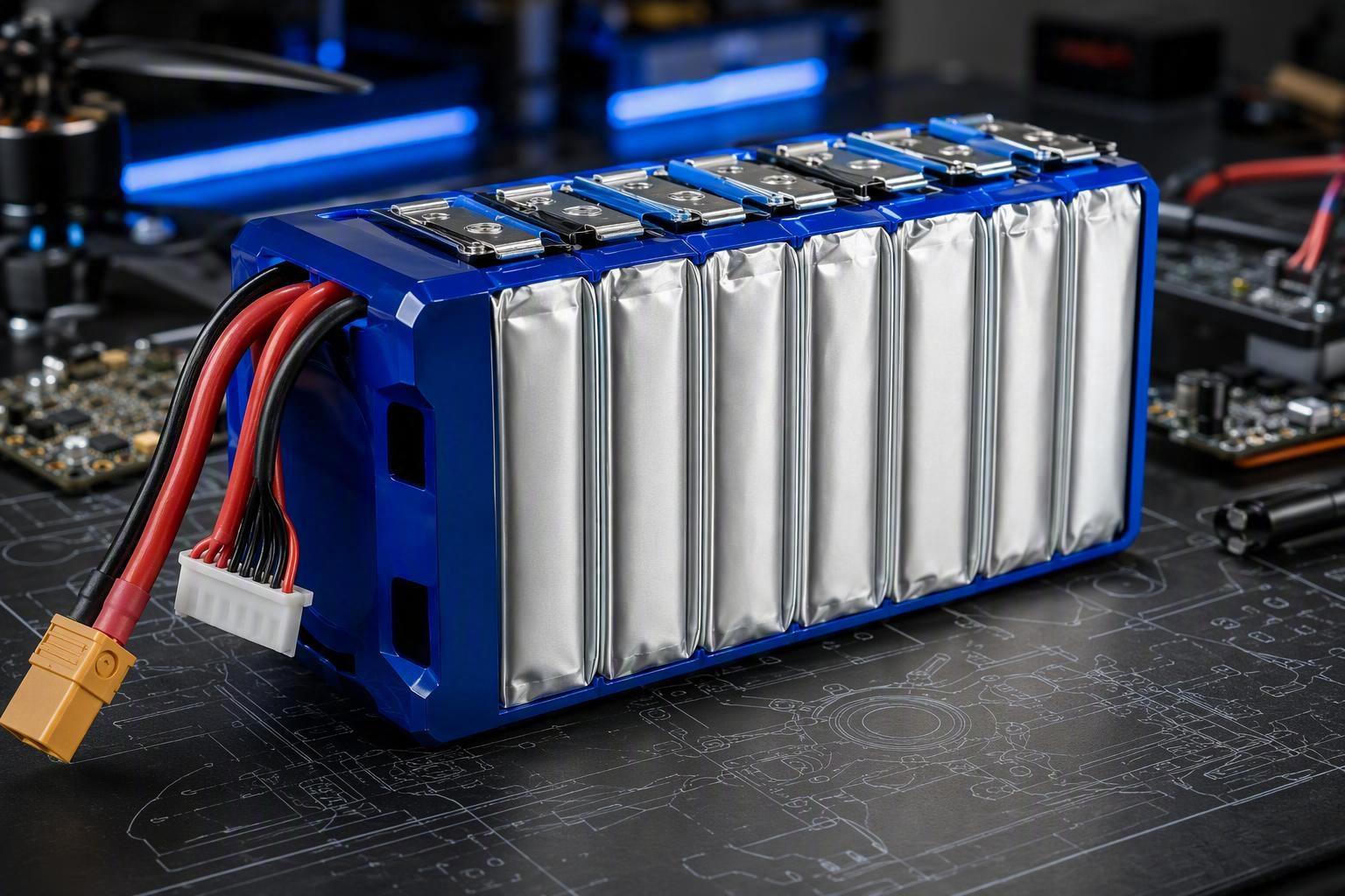
A cell specification describes a bare electrochemical component. A pack is an assembly: cells, plus busbars, high-current harnessing and connectors, a BMS with its sensing and switching hardware, an enclosure, cell holders, thermal interface material, and often potting or structural foam. These components add mass without directly contributing to electrochemical energy storage, so, all else equal, the finished pack typically has a lower gravimetric energy density than the cells it contains. The gap is set by integration design rather than by chemistry, since much of that added mass carries structural, thermal, or electrical protection functions the pack cannot omit. The size of the gap depends on the pack architecture and on how much mass is required for structural, thermal, electrical, and protection functions. For sizing, use measured pack-level energy density rather than applying a fixed cell-to-pack conversion factor.
For scale, commercial cells sit in fairly well-established bands: lithium iron phosphate (LFP) cells run roughly 150–200 Wh/kg, while high-energy nickel-rich chemistries such as NMC reach around 220–300 Wh/kg. Pack-level energy density lands below those figures because of the integration mass above — commonly working out to something like 60–80% of the cell figure, so a 300 Wh/kg cell can end up closer to 180–240 Wh/kg once it is built into a pack.
For sizing, only one number matters: the mass of the finished pack divided into the watt-hours it actually delivers. Anything else is a chemistry claim, not an aircraft input.
Nameplate Wh vs Mission Wh
Rated capacity is established under specified test conditions — including defined temperature and discharge conditions. Flight is the opposite profile. A cargo mission loads the pack hard at takeoff, modulates it through climb and cruise, and spikes it during gust recovery. Four factors then reduce or constrain the energy available to the mission — and each one is easy to overlook:
Rate-related losses. Sustained high current raises polarization and internal resistance, turning a share of stored energy into heat instead of thrust.
Temperature derating. Cold slows ion transport and raises interfacial resistance, cutting delivered capacity and terminal voltage. Heat accelerates parasitic reactions and shortens service life.
Ageing. Cycle and calendar life both raise internal resistance and reduce capacity. A new pack and the same pack after substantial service do not necessarily provide the same usable energy or power margin.
Operating SOC window. An aircraft and its BMS may define a usable state-of-charge window rather than exercising the full theoretical cell voltage range, protecting cycle life and preserving margin against cell imbalance.
Together, these four factors are what the sizing formula later calls the usable factor — the fraction of nominal pack energy you can actually count on in flight. In practice, that fraction often lands somewhere in the 70–90% range under real cargo-duty conditions, and lower at the edges of the temperature and current envelope. Keep them in mind when you reach Step 5.
Derive range from pack-level, mission-condition data. A cell datasheet tells you what the chemistry can do; it does not tell you what the aircraft can fly on.
Battery Mass: Why More Capacity Isn’t More Range
The Weight Feedback Loop
Adding capacity adds energy. It also adds mass, and, all else equal, added mass raises the power required to keep the aircraft in the air. For a multirotor in hover, induced power is commonly approximated as scaling with the 1.5 power of weight, all else equal. In a real aircraft, rotor efficiency, propeller geometry, drivetrain losses, and operating conditions also affect the actual relationship.
That relationship helps explain the diminishing returns operators observe in the field. For a given airframe and mission, additional battery mass usually produces diminishing endurance gains once the battery becomes a substantial share of takeoff mass. The practical battery size therefore depends on the aircraft and mission rather than simply on the largest pack that fits.
Where that balance sits depends on the mission. A platform flying short, heavy hops may be better served by a smaller pack that preserves payload capacity, while longer, lighter missions may justify a larger pack. Two operators flying the same airframe can legitimately end up with different specifications, so a pack should be sized against each operator’s own mission rather than offered as a single standard configuration. The practical consequence is that cargo drone range is a design variable you tune, not a specification you accept.
For platforms in the heavier payload classes, the heavy-lift battery selection framework covering 10–200 kg payload bands works through how endurance estimates change once pack mass starts competing with payload mass directly.
Payload vs Range: The Same Kilograms
The payload range trade-off is the most familiar constraint in this list and the most frequently misread. Published figures often pair the maximum payload with the maximum range as if the two occurred together. They do not.
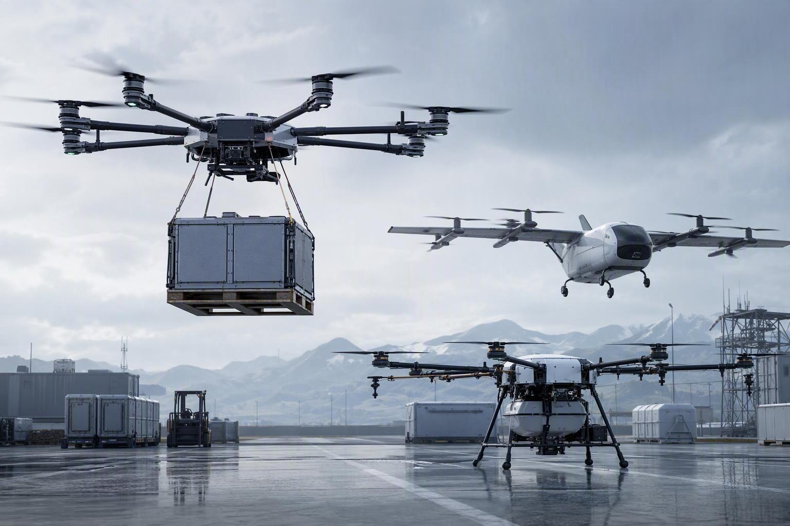
Every kilogram assigned to cargo is a kilogram unavailable to the battery, and vice versa, inside one fixed takeoff mass. This sets the defining asymmetry of cargo operations: for a given mission profile, the same aircraft may have substantially different achievable range at maximum payload and at a reduced payload.
Compare full-payload range, not headline range — the distance achievable with the cargo the mission actually requires, at the reserve the operation actually holds. Then ask what the figure assumed: test altitude, ambient temperature, wind allowance, and end-of-mission SOC should all be stated. Treat payload capacity as a curve rather than a limit, because a single maximum payload figure without its corresponding range is an incomplete specification. The fastest way to pressure-test a platform vendor is to request the payload-range curve and locate your own mission point on it. If the curve is unavailable, ask the platform supplier to provide the test conditions and the payload-range data needed to locate your own mission point.
Power Demand: Energy You Can’t Reach
Power demand is where a pack that looks adequate on paper often falls short in flight.
Terminal voltage under load equals open-circuit voltage minus the voltage dropped across internal resistance: V terminal = E ocv − I × R DC. At low current, the resistive drop may be relatively small. At the currents a heavy-lift cargo drone can pull during takeoff, aggressive climb, or gust recovery, voltage sag and resistive losses can become significant, and the battery’s actual voltage response is often more complex than a simple fixed-resistance model. At these current levels, voltage sag and resistive losses can become increasingly important, while the available voltage and power margin may narrow as the mission progresses.
Two things happen at once. Resistive heating scales with the square of current, so the energy lost to heat can grow disproportionately as demand rises. Terminal voltage can also fall. Terminal-voltage reduction may become a limiting factor because the aircraft’s power system typically operates within a defined voltage range. When sag carries terminal voltage below that threshold, the system may treat the pack as depleted regardless of the charge still inside it. Energy may still remain in the cells, but the aircraft may be unable to use it without crossing the system’s voltage limit.
A pack that passes a low-rate capacity test can still trigger early undervoltage protection during a full-payload climb. Size packs against worst-case mission current, not average current.
Why loaded endurance drops faster than mass alone explains: This is the mechanism behind the field observation that a cargo drone’s loaded endurance falls further below its unloaded endurance than the mass difference alone would predict. The gap comes from three interacting effects: more mass to lift, higher power demand under load, and a lower usable fraction of stored energy at higher current.
This is also why energy density and peak current must be read together. It is why the energy-density-versus-power-capability question cannot be settled on a datasheet. Higher energy density and high-rate capability can require different cell-design priorities, and a cell optimized for energy storage therefore still needs to be evaluated against the aircraft’s peak and continuous current requirements. If available power is insufficient for the mission, the consequences are not limited to slower flight: the flight controller may struggle to hold altitude and attitude, and in extreme cases power shortfall can contribute to height loss or loss of control. That is why energy density without the discharge capability to support it has limited operational value in a cargo platform. For a given mission, the range target, payload, peak current, thermal envelope, and reserve are typically coupled — a constraint set rather than a ranking.
DCIR also changes with temperature, SOC, and ageing, so voltage-sag margin should be evaluated against the relevant worst-case conditions in the mission envelope.
Flight Conditions: Temperature, Altitude, Wind
Adverse conditions can affect both propulsion efficiency and battery performance at the same time, so their combined effect should be included in the mission model.
At higher altitude, lower air density can reduce propeller thrust for a given operating point and increase the power required to produce the required thrust. Cold ambient temperature can raise cell resistance and reduce delivered capacity, while high current can generate additional heat within the pack. Wind and gust loading can add power spikes that increase both propulsion energy demand and battery losses through higher current, voltage sag, and heating.
For planning, specify the conditions the number applies to rather than arguing about the number. A mission envelope stating altitude band, ambient temperature range, wind allowance, and payload is a far stronger planning input than a single cargo drone range claim.
Outbound vs Return: Two Energy Profiles
One more split matters before you set reserve, because it changes the numbers the reserve is protecting. A cargo sortie is not flown by one aircraft in one configuration. It is flown by a heavy aircraft going out and a light aircraft coming back.
Outbound, the drone carries full payload at maximum takeoff mass. Hover and climb power are therefore higher, and cruise energy demand also increases relative to the lighter return leg. Return, the payload is gone. Lift requirement drops, motors generally operate at lower power, and energy demand per kilometre can fall relative to the loaded outbound leg — a commonly cited rule of thumb puts the unloaded return leg at roughly 60–80% of the loaded leg’s energy per kilometre, though the exact gap depends on how much of takeoff mass was payload.
Three planning consequences follow. The outbound leg should not be hidden inside an average: it carries the maximum payload and often represents the highest-power segment of the mission. Relying only on a mission-average power figure can under-size the pack for the high-demand segments that determine the aircraft’s operating margin. The return leg is cheaper but never free: airframe drag, avionics, cargo-handling systems, and the reserve itself all continue to consume energy, and headwind on the return can erase the entire theoretical advantage. For delivery operations, a symmetric out-and-back range figure is not enough to describe how the aircraft performs when payload and mass change between the two legs.
Reserve: Energy That Flies but Never Delivers
Reserve is the operational margin held back from the mission — for the return leg, for a diverted landing site, for the additional energy consumed by unexpected headwind, or for a battery that has aged faster than planned.
Its size is a risk decision, not a physics constant. Reserve should be defined from the mission, contingency options, operating procedures, aircraft capabilities, and applicable regulatory requirements. Define the requirement for the specific operation rather than applying a generic percentage, and establish the figure from its operating approval and contingency plan.
As a starting reference, many operations settle in the region of 20–30% of pack energy for routine, short-range missions, with longer cross-region, high-altitude, or adverse-weather routes pushing toward the upper end or beyond. Treat those numbers as a benchmark to adjust, not a rule to copy.
The sizing formula is deliberately blunt:
Usable mission energy = nominal pack energy × usable factor × (1 − reserve fraction)
Where the usable factor accounts for temperature derating, rate derating, and ageing, and the reserve fraction accounts for the mission’s contingency policy. Both terms should be documented, because undocumented derating is how a range calculation becomes a planning failure rather than a conservative estimate.
Express reserve as energy or flight-time margin rather than as a fixed distance. The distance covered by a given energy reserve can change with aircraft mass, wind, and operating conditions.
How to Estimate Cargo Drone Battery Requirements
The procedure below turns those six variables into a first-order pack energy target. Mission mass covers the payload and battery-mass variables; power and flight conditions feed the energy and current figures; derating and reserve close it out. The result is deliberately conservative and is meant to be tightened with measured data as the programme matures. Worked figures are illustrative assumptions.
Step 1 — Define the mission envelope
Outbound distance, return distance, payload mass, cruise speed, altitude band, ambient temperature range, wind allowance. Example assumption: 30 km outbound, 30 km return, 40 kg payload, 18 m/s cruise, sea level to 500 m, 5 to 35 °C, 8 m/s headwind allowance outbound.
Step 2 — Establish total takeoff mass
Airframe, propulsion, avionics, payload, and candidate pack mass. Example assumption: 55 kg airframe and systems, 40 kg payload, 45 kg pack candidate = 140 kg takeoff mass.
Step 3 — Get measured power figures at that mass
From the airframe’s own test data, take hover power, cruise power under representative wind conditions, and peak current during climb and gust recovery. If you can, log an actual load current profile from a representative flight — that log is what the supplier section later asks for, and it replaces every estimate in this step. Do not substitute estimates from a similar aircraft; mass, rotor geometry, and motor efficiency all shift the numbers.
Step 4 — Compute the energy required to complete the planned mission
Outbound energy uses the power required at full payload under the specified wind condition, multiplied by outbound time, plus climb energy. Return energy uses the power required at reduced mass over the return time, using the wind and flight-profile assumptions specified for that leg. Add hotel loads — avionics, telemetry, cargo actuators, onboard computing — across total flight time. This mission energy is the energy needed to fly the planned mission and does not yet include any reserve.
Step 5 — Apply derating and reserve
Required nominal energy = mission energy ÷ usable factor ÷ (1 − reserve fraction). The usable factor represents the fraction of nominal pack energy validated as available under the specified operating condition, including relevant temperature, discharge-rate, and ageing effects; the reserve fraction is held back for contingency use. Use the validated usable factor for the worst operating condition in your mission envelope.
Step 6 — Check power, not only energy
Confirm the candidate pack can deliver peak mission current while staying above the system undervoltage threshold during the highest-demand outbound segments, including the relevant low-SOC and worst-temperature conditions. This check eliminates many otherwise reasonable packs.
Step 7 — Iterate on pack mass
Pack mass assumed in Step 2 changes the power required in Step 3. Repeat the calculation until the assumed pack mass and resulting power requirement converge. If the calculation cannot converge within the aircraft’s mass and power limits, the mission may lie outside the current airframe configuration’s practical envelope.
Running that exercise against your own mission data rather than a generic example is standard sizing work; a load current profile and mission envelope are enough to start.
What to Send a Battery Supplier
A supplier sizing a pack without mission data is working from assumptions. The package below is what a pack engineer needs to size the system. This information allows the supplier to evaluate the pack against the actual mission rather than against a generic application.
Mission definition: payload mass and the outbound/return mass profile; distances per leg plus any loiter requirement; cruise speed and altitude band; ambient temperature range for operation and storage; the wind and gust allowance the operation must tolerate.
Electrical requirements: the voltage band the aircraft and its power electronics require; continuous and peak current, with the duration of the peak specified; a load current profile logged from a representative flight if one exists; the undervoltage and overvoltage thresholds the flight controller enforces; and the charge rate and turnaround time the operation needs.
Mechanical and integration requirements: volume envelope and mounting interface; connector types and current rating; the mass ceiling and whether it is hard or negotiable; IP rating, ingress, and vibration environment.
System and compliance requirements: the BMS communication protocol the flight controller expects, including CAN or SMBus telemetry requirements (or UART where supported) and how SOC, cell voltage, and fault flags are reported; the airworthiness or certification basis the platform is pursuing; and the transport documentation the fleet’s routes require.
That last item is not a formality. For cross-border deployment, confirm the transport testing and dangerous-goods documentation required for the battery and the route, including applicable UN38.3 requirements for lithium batteries in logistics operations. A pack that cannot be shipped to the operating region has an operational range of zero regardless of its energy content. Market-specific product standards or certifications should be identified against the destination market and the aircraft programme rather than requested as a generic checklist.
Cargo Drone Range: Common Misconceptions
Pack capacity sets range:
Capacity sets a ceiling on the energy available. The distance achieved is what remains after mass penalty, power limits, environmental derating, and reserve are applied to it.
Cell energy density is the number to compare:
Pack-level energy density is the number the aircraft carries. Cell figures describe an electrochemical component the aircraft will never fly with.
Higher energy density always means longer flights:
Higher energy density and high-rate capability can require different cell-design priorities. If the design cannot deliver peak mission current without triggering undervoltage protection, the extra watt-hours remain unreachable.
Range scales with capacity:
Adding capacity can improve endurance initially, but the benefit diminishes as battery mass becomes a larger share of takeoff mass and may eventually become counterproductive for a given aircraft and mission.
Reserve is overhead you can trim for performance:
Reserve is what covers a headwind you did not forecast or a pack that aged faster than planned. Trimming it converts a conservative mission plan into an unhedged one.
Reserve is a fixed percentage of the pack:
As covered above, reserve is a mission-specific risk decision, not a constant. Set it before you calculate required pack energy rather than applying it after the range estimate.
From Sizing to a Battery Programme
The procedure above only works when the inputs are real. Range constraints are not a cell-specification problem so much as an integration problem, and integration is where the pack-level numbers are decided — energy content at pack level, current delivery at mission peak, and the structural and thermal mass the pack adds.
That is the loop a pack supplier can either support or sidestep. Working from a cell datasheet and an application label tends to produce a generic answer. Working from your load current profile, your mission envelope, and your peak-current duration allows a candidate pack to be evaluated against the real inputs, including whether the voltage-sag margin holds through the highest-demand outbound segments.
Three inputs are enough to start:
Your load current profile — logged from a representative flight if you have one, or the mission envelope if the programme is earlier
Peak current and its duration, including the climb and gust-recovery events that define your worst case
Your mission envelope — payload, distances, altitude band, ambient temperature range, and reserve policy
From there, a pack-level check against measured cell and pack data can show where the voltage-sag margin is thin and what architecture fits the airframe’s mass budget. This is the same starting point Herewin‘s engineering work on custom UAV packs uses, sizing the architecture against the airframe’s mass and power budget rather than a datasheet figure.
Sizing a pack correctly is considerably cheaper than discovering the gap on a loaded outbound leg.

 ไทย
ไทย  English
  Español
  한국어
한국어  Deutsch
  Français
  日本語
日本語  Русский
  Bahasa Indonesia
  العربية
  Português do Brasil
  Italiano
  Nederlands