


In the accelerating global energy transition, energy storage systems have become the core backbone for distributed PV, commercial peak-shaving, and residential backup power. Stackable LiFePO4 battery systems, with their modular architecture and high spatial efficiency, are rapidly replacing traditional all-in-one units as the strategic choice for modern enterprises. However, true “flexible installation” is not a matter of arbitrary deployment; it demands a structured engineering approach built on three pillars: precise planning, standardized operation, and meticulous maintenance. By adopting these professional benchmarks, you can balance modular scalability with rigorous safety standards, ensuring your energy assets deliver maximum reliability and long-term ROI in a competitive market.
要点
Prioritize environmental stress management by ensuring optimal temperature and ventilation to prevent thermal runaway and safeguard the battery’s chemical integrity.
Adhere to standardized mechanical fastening protocols to minimize contact resistance and ensure structural stability during long-term operation.
Integrate a high-performance Battery Management System (BMS) for real-time monitoring of health metrics and automated module equilibrium.
Maintain strict adherence to global compliance frameworks like UN38.3 and IMDG to ensure safe transport and mitigate international logistics risks.
Implement a proactive maintenance regime, including routine hardware inspections and electrical audits, to maximize system ROI and lifespan.
Site Engineering & Infrastructure Benchmarks
Before deploying any stackable LiFePO4 modules, a comprehensive site audit is mandatory to define the installation scenario—whether it is Residential (Home ESS), Small Commercial & Industrial (C&I), or Large-scale Industrial Parks. This initial assessment ensures that the infrastructure meets the specific environmental and safety demands of the target application.
Environmental Stress Management: Temperature & Ventilation Standards
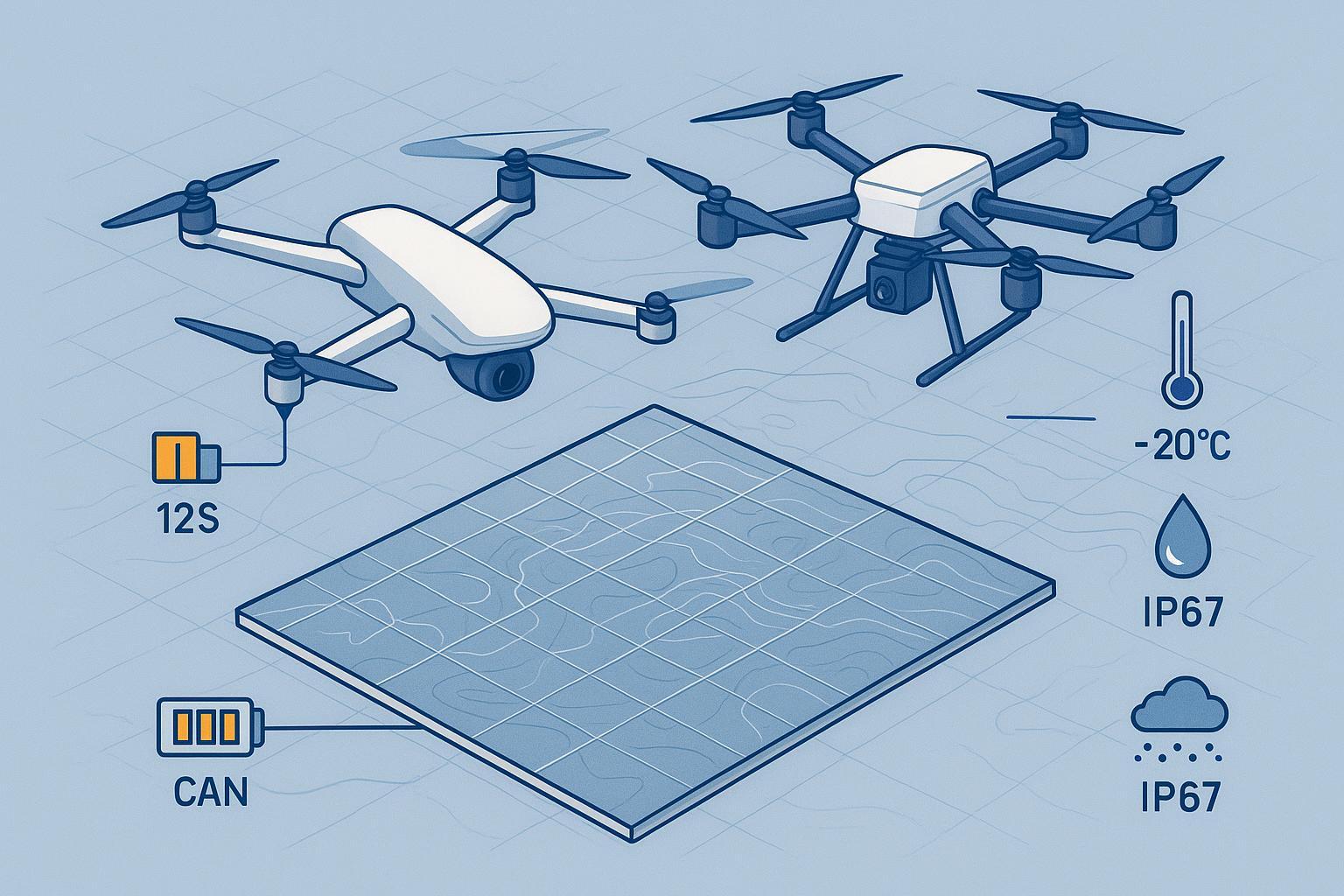
To ensure long-term system stability, the installation environment must strictly adhere to specific engineering benchmarks. The core operating temperature must be maintained between 0-40°C, with a relative humidity of ≤85%. In high-humidity regions, dedicated dehumidification equipment is mandatory; conversely, in extremely cold climates, insulation measures or verification of low-temperature startup capabilities must be prioritized.
Ventilation is a critical factor in thermal management. The installation area must ensure at least three air changes per hour, with a minimum of 50cm of clearance reserved above the battery stack for heat dissipation. Furthermore, the system must be isolated from gas equipment and heat sources—such as radiators or distribution boxes—to prevent external thermal interference with the battery’s chemical stability.
Structural Load-Bearing & Infrastructure Integrity
The structural integrity of the site must be meticulously verified against the high physical density of the modular system. To prevent structural fatigue or catastrophic imbalance, the following infrastructure benchmarks must be met:
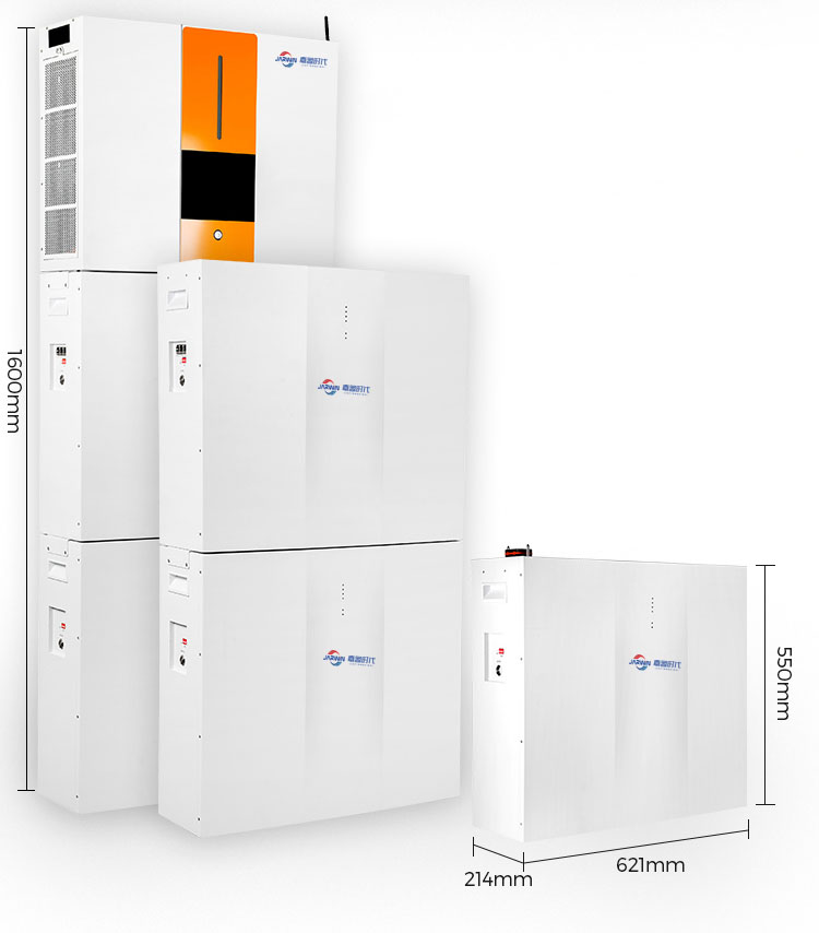
Load-Bearing Capacity: A single stackable module typically weighs between 45kg and 90kg. For a standard 4-layer configuration, the total system weight can reach up to 180kg. Consequently, indoor flooring must meet a concrete strength benchmark of at least C20 to support the concentrated static load.
Foundation Readiness: The surface must be level. If a horizontal error >2mm/m is detected during the site audit, procurement of 5–10mm rubber leveling pads is mandatory to ensure future stress distribution.
Outdoor Environmental Hardening: For outdoor deployments, modules with an IP54 rating or higher are mandatory. These must be supplemented by protective rain sheds and specialized lightning protection grounding to ensure resilience against localized weather stress.
Technical Execution: Precision System Integration
From Foundation to Stacking: Mechanical Fastening Standards
The structural stability of a stackable LiFePO4 system depends on precise mechanical execution during the foundation and stacking phases. To ensure the center of gravity remains aligned and the system operates safely, the following engineering standards must be met:
Installation Base Alignment: Before stacking, the mounting base must be positioned according to the center and horizontal markings. The base must be secured to the floor using expansion bolts, ensuring a horizontal error of ≤2mm/m. If the surface is uneven, 5–10mm rubber leveling pads should be utilized to prevent uneven stress distribution.
Precision Stacking Protocol: Modules should be stacked layer by layer, ensuring perfect alignment with the positioning pins to avoid any structural offset. A 5cm ventilation gap must be maintained between modules to facilitate heat dissipation.
Mechanical Fastening Specifications: Each module must be secured with at least four M6 bolts. To minimize contact resistance and prevent thermal hotspots, use a calibrated torque wrench to tighten these bolts to a specific value of 15–20N·m.
Long-term Stability Reinforcement: After fastening, apply 704 silicon rubber to the bolts to provide high-temperature vibration resistance and prevent loosening over time. Always adhere to the stacking limit—typically ≤4 layers—to maintain structural integrity.
Electrical Connectivity & EMI Mitigation Strategy
Precision electrical integration is paramount to system safety and performance. All wiring must adhere to the absolute sequence: DC before AC, Positive before Negative, and Grounding before Wiring. Before starting, verify that all equipment is powered down and use a multimeter to ensure zero residual voltage.
DC Interconnection & Parallel Wiring: Use high-quality copper cables (typically 35mm²) and professional busbars to parallel the modules. Ensure terminals are tightly secured and wrapped with insulation tape or protective caps to prevent accidental short circuits. A 500V insulation resistance test must be performed, with a passing value of ≥10MΩ.
System Grounding Architecture: Implement a TN-S grounding system using copper cables (≥16mm²). The grounding electrode should be buried at a depth of ≥0.8m, ensuring a grounding resistance of ≤4Ω to provide a reliable fault current path. For outdoor setups, an SPD (Surge Protective Device) is mandatory to guard against lightning strikes.
EMI Mitigation & Signal Integrity: To eliminate electromagnetic interference, maintain a physical separation of ≥30cm between DC and AC power cables. All communication lines (CAN/RS485) must use shielded cables, with the shielding layer grounded at both ends to ensure stable BMS data transmission.
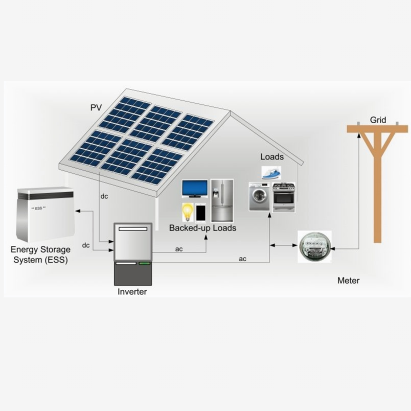
Inverter & Solar Integration: Connect the battery busbar to the PCS (Power Conversion System) DC input, ensuring clear labeling for all polarity. Verify that the PCS parameters are calibrated to LiFePO4-specific thresholds, such as an overcharge protection voltage of 58.4V and over-discharge at 44V.
Quality Assurance & Commissioning Protocols
BMS Networking & Automated Module Identification
To ensure high-performance integration, the Battery Management System (BMS) must be meticulously configured to communicate with the Power Conversion System (PCS) and monitoring terminals.
The following table outlines the engineering standards for system networking and automated identification:
特徴 | Technical Specification & Standard | Operational Logic |
Communication Interface | CAN / RS485: Utilizing shielded cables with dual-ended grounding; Wireless: Signal strength ≥ -60dBm. | Connect the BMS to the PCS and monitoring terminal to enable high-speed data exchange. |
Automated Identification | Automatic detection of module quantity, total capacity, and real-time voltage. | Follow the power-up sequence: Close the battery DC switch first, then power on the PCS. |
Voltage Equilibrium | Inter-module voltage variance must be maintained at ≤0.05V. | If variance exceeds the limit, run 2–3 charge/discharge cycles to activate auto-balancing. |
Safety Thresholds | Overcharge: 58.4V; Over-discharge: 44V; Overtemperature: 60°C. | Verify thresholds by simulating abnormal conditions to confirm the BMS protection trigger. |
The Acceptance Protocol: Resistance & Equilibrium Tests
The acceptance protocol is a systematic framework designed to verify that the stackable LiFePO4 system meets rigorous safety and performance engineering standards. This phase ensures that every component is validated against the approved design before final deployment.
Test Category | Technical Acceptance Standards | Methodology |
Insulation Resistance | Insulation Resistance: ≥10MΩ | Use a 500V insulation resistance meter to test the DC circuit; ensure no damage to cable sheaths. |
System Grounding | Grounding Resistance: ≤4Ω | Verify the TN-S system’s integrity and ensure the grounding electrode is buried at a depth of ≥0.8m. |
Voltage Equilibrium | Variance: ≤0.05V | Check voltage balance across all modules; perform 2-3 charge/discharge cycles if variance exceeds limits. |
Capacity & Stability | Retention: ≥95% | Complete a 72-hour continuous grid-connected trial run (for large ESS) and record 3 charge/discharge cycles. |
Final Checks & Documentation
Before the official system handover, a methodical final inspection is required to mitigate operational risks and verify that the installation meets engineering benchmarks:
Mechanical & Electrical Verification: Confirm all M6 bolts are tightened to 15-20N·m with 704 silicon rubber applied. Ensure DC/AC cable spacing maintains a ≥30cm isolation gap to prevent EMI.
BMS & PCS Logic Calibration: Verify that system-wide protection thresholds are active, specifically for overcharge (58.4V), over-discharge (44V), and over-temperature (60°C).
Safety Infrastructure Audit: Confirm the presence of MF/ABC8 dry powder extinguishers and verify the site maintains a ventilation rate of at least 3 air changes per hour.
Documentation Archival: Compile all UN38.3 test reports, product manuals, and signed acceptance logs into a permanent project file for future O&M.
Risk Management, Compliance & Asset Longevity
Global Compliance: UN38.3 and IMDG Regulatory Framework
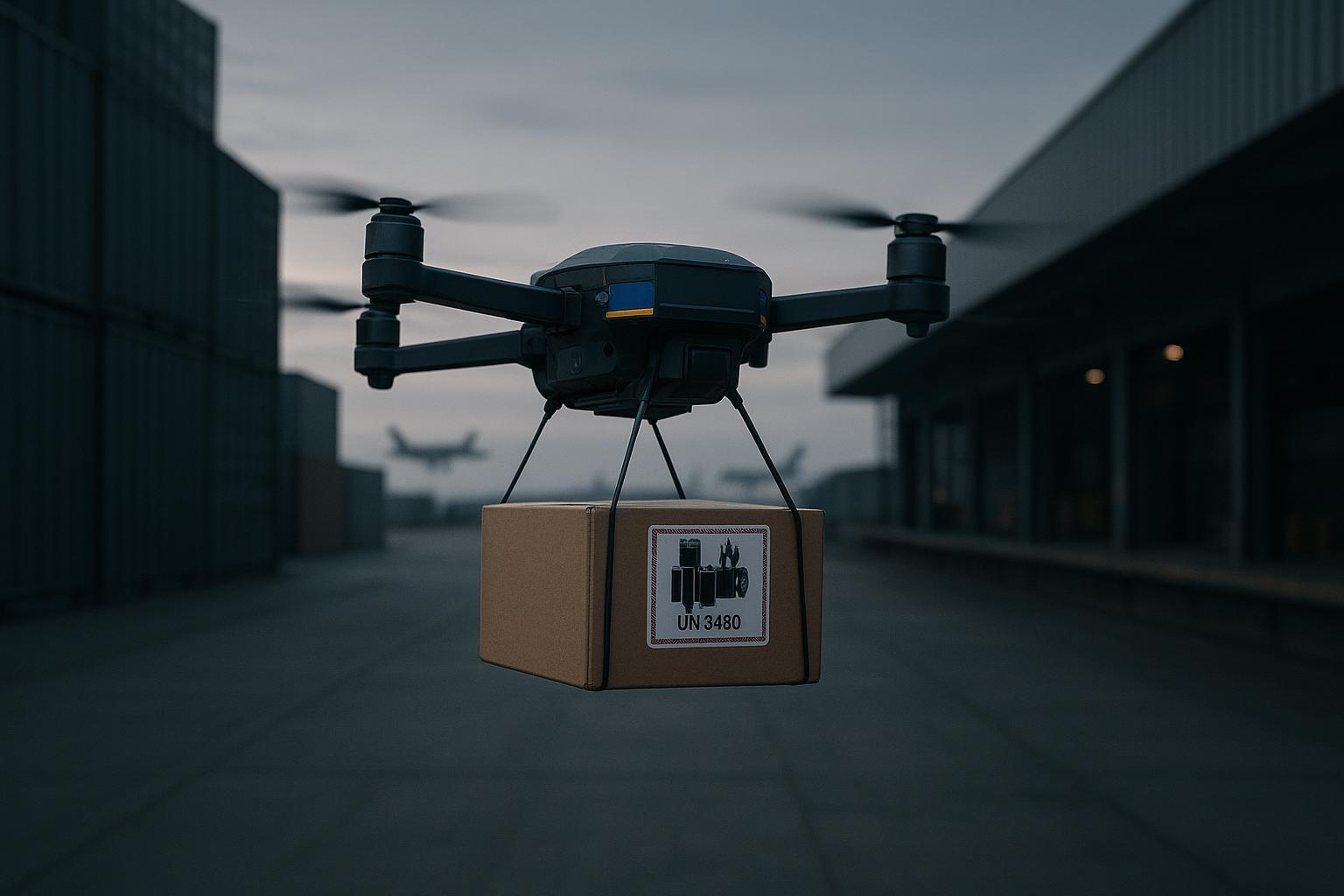
When deploying stackable LiFePO4 modules, adherence to global regulatory frameworks is the cornerstone of risk management and asset protection. Compliance with UN38.3 and the IMDG Code ensures that the system meets the highest safety standards for international transport, handling, and long-term deployment.
Requirement Category | Technical & Regulatory Standards | Impact on Asset Security |
Safety Verification | Batteries must pass rigorous tests, including thermal cycling, vibration, shock, and overcharge (58.4V) protection. | Minimizes the risk of thermal runaway and internal cell degradation during operation. |
Packaging & Handling | Adherence to UN38.3 certified packaging and Class 9 Dangerous Goods handling protocols. | Prevents mechanical damage and electrolyte leakage before the system reaches the site. |
認証 | Valid UN38.3 test reports and aviation/maritime safety appraisals are mandatory for all modules. | Ensures global project eligibility and mitigates legal and insurance liabilities. |
Strict adherence to these frameworks reinforces your organization’s reputation for engineering excellence. Beyond logistics, these standards define the “Safety Red Lines” for the entire lifecycle of the battery system, from arrival to 72-hour trial operation.
Troubleshooting & Lifecycle Maintenance
Operational resilience depends on rapid diagnosis and adherence to the engineering maintenance manual:
BMS Identification Failure: Verify CAN/RS485 link integrity and restart the BMS. If issues persist, initiate the module replacement protocol.
Abnormal Charging/Discharging: Inspect cable terminations for mechanical integrity. Re-verify protection thresholds (58.4V/44V); if capacity fade exceeds 5%, perform cell-level diagnostics.
Thermal Management: Clear heat dissipation pathways if temperatures exceed 45°C. If the system triggers a 60°C shutdown, verify cooling fan status before restart.
Proactive Asset Management: Maximizing System Lifespan
To maximize the ROI and operational lifespan of a stackable LiFePO4 installation, a proactive maintenance regime is essential. Adopting these manufacturer-verified practices reduces the Total Cost of Ownership (TCO) and ensures long-term reliability:
Routine Data Audits (Weekly): Utilize intelligent monitoring systems (SCADA/EMS) to audit real-time metrics. Immediate intervention is required if module temperatures exceed 45°C or if significant voltage variances are detected.
Preventive Maintenance (Semi-Annual): Every six months, perform a comprehensive hardware audit. This includes using a calibrated torque wrench to re-tighten all M6 bolts to 15-20N·m and verifying the status of the Surge Protective Device (SPD).
Environmental Integrity: Maintain the installation site to prevent dust accumulation, which can impair heat dissipation. Use dry cleaning methods only; direct water contact is strictly prohibited to prevent short circuits.
Cycle Optimization: Manually initiate the BMS balancing function periodically to ensure cell equilibrium. To extend the battery’s chemical life, avoid prolonged deep discharges and maintain a consistent SOC range.
The Definitive Installation Checklist
Energy storage installation involves high-voltage risks. To eliminate potential hazards and ensure onsite security, the following safety protocols are mandatory for all personnel throughout the installation process:
Certified Personnel: All installers must hold a valid Electrician’s License and undergo specialized pre-job safety training on energy storage system architecture.
De-energized Operation: Before any electrical connection, all power sources must be disconnected. Always use a multimeter to verify zero residual voltage; live-line work is strictly prohibited.
Short-circuit Mitigation: Disconnect all loads before wiring and ensure positive/negative terminals never cross. Ensure all tools are fully insulated and kept away from terminal interfaces during the installation process.
Emergency Protocols: In the event of leakage or fire, shut down the system and disconnect power immediately. Use MF/ABC8 dry powder extinguishers only; direct water contact is strictly prohibited.
In summary, the successful deployment of a stackable LiFePO4 battery system is a strategic integration of precise planning, standardized technical execution, and rigorous maintenance. By strictly adhering to the engineering benchmarks and safety protocols outlined in this guide, enterprises can transform modular hardware into a highly reliable energy asset.
To ensure optimal performance and long-term asset security, prioritize the following core operational aspects derived from our standard operating procedures:
Final Compliance & Performance Metrics | Key Engineering & Safety Focus | Technical Benchmark |
Mechanical Stacking | Ensure base leveling and secure M6 bolts with anti-loosening measures. | Torque: 15–20N·m; Error: ≤2mm/m. |
Electrical Integrity | Verify DC/AC isolation and system-wide insulation. | Insulation: ≥10MΩ; Spacing: ≥30cm. |
System Equilibrium | Monitor BMS data for module consistency and safe operational thresholds. | Voltage Variance: ≤0.05V; Temp: <45°C. |
Compliance & Safety | Adhere to international transport and fire safety standards. | Grounding: ≤4Ω; Standards: UN38.3/IMDG. |
Prioritizing these professional strategies ensures that your stackable LiFePO4 installation is safe, efficient, and ready to support your long-term energy goals.
よくあるご質問
What is the ideal temperature range for LiFePO4 battery installation?
The installation environment must be maintained between 0-40°C with a relative humidity of ≤85%. Proper thermal management and 50cm top clearance are required to prevent thermal runaway.
How often should I perform maintenance on my battery system?
Conduct weekly data audits for thermal anomalies and semi-annual physical inspections to re-tighten bolts to 15-20N·m. Always verify the SPD and grounding integrity during these checks.
What safety measures should I implement during installation?
Follow the strict operational sequence: DC before AC, Positive before Negative, and Grounding before Wiring. Maintain a ≥30cm isolation gap between power and signal cables to mitigate EMI.
Can I stack LiFePO4 batteries vertically?
Yes, but do not exceed 4 layers (approx. 180kg). Ensure the base is level within ≤2mm/m and secured to a C20 concrete floor.
How do I monitor the health of my battery system?
Utilize a BMS with CAN/RS485 support for real-time monitoring. The system must maintain an inter-module voltage variance of ≤0.05V and operate within calibrated protection thresholds (e.g., 58.4V for overcharge).
こちらも参照
Essential Guide to RV Lithium Battery Compatibility Upgrades
Maximizing Safety and Efficiency in Charging 18S Drone Batteries
2025 FPV Drone Battery Guide: Selection, Care, and Performance
Top Tips for Extending Lithium Battery Life in EVs and Golf Carts
Transforming Drone Safety with Smart BMS and Long-Lasting Batteries