











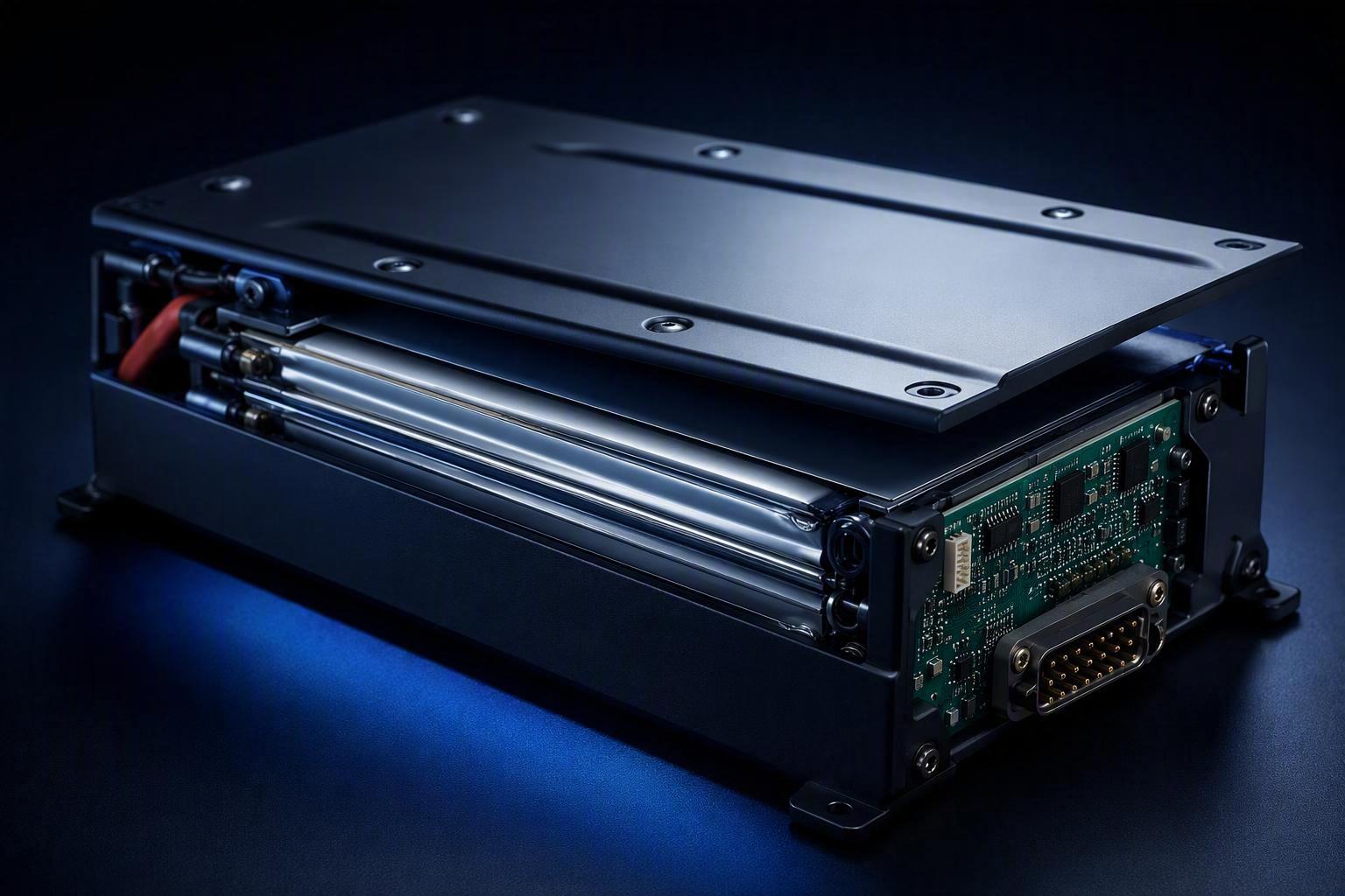
A UAV program reaches the battery-sourcing phase. The airframe dimensions are approved, the propulsion system is selected, and the motor–ESC pairing is locked. The inquiry goes out to a battery supplier, a PACK design comes back — and two months later, the integration team finds the battery 180 grams over budget, the connector pinout incompatible with the power distribution board, and the BMS outputting none of the telemetry fields the flight controller expects.
The issue is not necessarily the supplier’s design capability. In most cases, the brief simply did not define enough of the aircraft’s real requirements. Send an inquiry with only a cell count and a capacity figure, and the supplier fills in every remaining decision with their own defaults — defaults that may not match your airframe, your power electronics, your communication architecture, or your target market’s certification requirements. By the time the mismatch shows up, enclosure tooling is often already underway.
That is the gap this article addresses. Below are the ten parameters UAV teams should define before contacting a custom PACK supplier, covering electrical architecture, mechanical integration, power management, BMS communication, charging, environmental performance, and compliance. The aim is not to eliminate iteration, but to make sure the requirements your supplier works from actually describe the aircraft you are building. A capacity figure alone says nothing about how the battery will be used, and the brief is most useful when it reaches the supplier early — alongside platform design, not after the aircraft has already been shaped around assumptions. That timing is the reason the next section matters as much as the parameters themselves.
Why the Battery Needs to Be Defined Alongside the Aircraft, Not After
Battery development belongs alongside the aircraft, not after it. The battery has a direct impact on the weight budget, the center-of-gravity window, the electrical interface, and parts of the certification process — so its electrical, mechanical, and operating requirements touch multiple systems at once.
That is why structural, propulsion, electrical, and battery teams all need to work from the same requirements. When each team assumes its own battery characteristics, those assumptions rarely converge, and the brief that reaches the supplier contains conflicts it cannot resolve on its own.
Defining the ten parameters below early creates one shared reference for every discipline — and gives your supplier enough to start cell selection and PACK architecture in parallel with platform development.
10 Parameters to Define Before Custom PACK Development
Voltage Platform: Define the Full Operating Range
The number of cells in series determines the battery’s voltage platform. For most industrial UAV programs, this means specifying not just the nominal configuration (6S, 12S, 24S, 32S) but the complete operating voltage window the aircraft’s electronics must accommodate. A standard lithium cell sits at roughly 3.7V nominal and 4.2V fully charged, so a series count alone describes only one point along that window — not the range your electronics will actually see.
The voltage window you define sets ESC input voltage ratings, motor KV and winding specification, power module input range, low-voltage warning and protection thresholds in the flight controller, and the charging architecture. Every front-end component should be matched against the full window, not just the nominal figure, which is why the ESC, motor, and power module voltage ratings belong in the same locked set of requirements.
What to provide to your supplier:
Parameter | Why It Matters |
|---|---|
Nominal voltage (V) | Sets the baseline for all electrical sizing |
Maximum charging voltage (V) | Determines cell balancing and charge circuit design |
Minimum operating voltage (V) | Drives cutoff threshold in the BMS |
Low-voltage warning threshold (V) | Flight controller alert logic |
Low-voltage protection threshold (V) | BMS hard-cutoff setting |
Connected component voltage limits | ESC, power electronics, avionics rails |
One more point follows from the table. A higher cell count can reduce the current required for a given power level, which may allow smaller conductors and lower current-rated interfaces. But voltage is a system compatibility constraint, not a performance ranking. If an ESC cannot accept the battery’s maximum fully charged voltage, the selected series configuration will not be compatible — even when its nominal voltage appears suitable.
Continuous and Peak Current: Match the Battery to Real Flight Loads
Capacity specifies how much energy the battery stores. Current delivery capability specifies whether the battery can provide the power the aircraft actually demands during each flight phase.
Current requirements drive cell selection (discharge capability vs. energy density tradeoff), BMS current limits, internal resistance specification, conductor sizing, connector rating, and thermal management.
Capacity and discharge capability are separate requirements that are often treated as one. Capacity determines how long the aircraft can stay aloft; discharge capability determines how much power the battery can actually deliver while it does. A cell or PACK can meet its rated capacity while still delivering insufficient current, so the two numbers need to be specified independently.
A UAV’s current demand is not constant. Hover with payload, takeoff, rapid climb, and evasive maneuvering each impose different load profiles. Peak current can differ substantially from average hover current, depending on the aircraft architecture, payload, and flight condition — and the duration of that peak determines how much thermal and electrical margin the PACK needs.
What to provide:
Maximum continuous current (A) or continuous power (W)
Peak current (A) or peak power (W)
Peak duration (seconds) — a 200A peak for 100 ms is a very different design constraint than 200A for 5 seconds
Required BMS current limit (A)
Operating temperature during high-load phases
C-rating alone does not establish the real current capability of the finished PACK. Cell characteristics, internal resistance, temperature, state of charge, BMS current limits, and PACK design all matter — so the rating is not a reliable basis for judging whether a battery can meet the aircraft’s actual load profile.
If peak current requirements are not defined before cell selection, the supplier may choose cells optimized for energy density rather than power capability. The result is a PACK that meets its capacity specification but delivers inadequate peak output — visible in flight as voltage sag, propulsion reduction, or BMS overcurrent trips under load.
This is a front-loaded constraint, not something that firmware tuning can fully recover. If the continuous and peak current requirements are set too low, the fix is a different cell with a higher discharge capability, a revised BMS current-limit strategy, and new conductor sizing — all structural changes rather than software adjustments.
Target Flight Time: Size the Battery Around the Mission
Flight time is often treated as an output of battery selection — a figure you calculate after choosing the PACK. It is more useful as an input: a mission constraint that helps determine the usable energy and weight budget the battery must fit within.
The flight-time target shapes the capacity specification, weight allocation, reserve margin, and the tradeoff between energy density and discharge rate in cell selection.
Define flight time at the mission level, not at the laboratory level:
Mission flight time: Time aloft at operational payload, not at zero load
Reserve time: Margin reserved for return, contingency, or emergency hold
Hover vs. cruise split: Power demand differs significantly between these phases for most multirotor and hybrid platforms
A rough energy estimate uses the formula: usable battery energy ÷ average aircraft power ≈ estimated flight time. This is an approximation, not a prediction. What actually reaches the aircraft is usable capacity, not the nameplate figure — it is reduced by discharge efficiency, the losses incurred by the operating profile, and the environmental conditions the platform flies in. Average power itself varies with payload, altitude, wind, and flight mode, and a larger PACK adds weight that the propulsion system must lift — so the practical flight-time benefit of additional capacity depends on how much extra weight the aircraft must carry.
To keep this grounded, share the target mission flight time together with the maximum payload, the estimated average power consumption for each flight phase, the reserve requirement, and the maximum battery weight the aircraft can carry. These figures let the supplier size the pack around the mission rather than around a nominal capacity.
Under-sizing the capacity leaves the aircraft short of its mission requirement. Over-sizing it adds weight that the propulsion system must lift, uses up payload allocation, and can reduce maneuverability. Both directions ultimately reduce usable performance, which is why the flight-time target belongs in the requirements brief rather than in a post-selection calculation.
Battery Dimensions and Weight: Lock the Mechanical Envelope Early
Once electrical requirements are estimated, mechanical integration constraints define what kind of PACK architecture is physically achievable within the airframe. The battery is one of the largest and heaviest single components in most UAVs, which makes the bay envelope and the weight budget front-loaded constraints for the airframe — they shape the platform rather than adapt to it late in the program.
The mechanical envelope constrains cell count and format options, structural housing design, connector orientation, cable routing, cooling space, and whether an off-the-shelf or fully custom enclosure is required.
Dimensional requirements for an OEM program go beyond length × width × height. The supplier also needs to understand:
Mounting method and mounting point locations
Connector access direction (top-entry, front-entry, side-entry)
Cable routing path and strain relief requirements
Clearance to adjacent structures under vibration
Whether the battery compartment includes a thermal interface or is sealed
Ingress protection requirement for the enclosure (dust, water, washdown)
Weight constraints are equally important. Battery weight contributes directly to maximum takeoff weight, affects payload allocation, changes the loading on the airframe structure, and influences propulsion sizing. If the battery weight budget shifts late in the program, the cascade includes revised propulsion analysis, structural revalidation, and potentially changes to the battery compartment mounting.
For OEM programs, provide the mechanical envelope as a dimensioned drawing or 3D envelope rather than nominal figures alone. Tolerances, required clearance, and any cell or enclosure-specific mechanical considerations should be reviewed before the PACK dimensions are finalized.
Center of Gravity: Integrate Battery Placement Into Aircraft Layout
The battery is typically one of the heavier concentrated masses in the aircraft. Its mass and mounting location directly affect the aircraft’s center of gravity and weight distribution — and in turn the balance and stability margins, the loading across the motors, how freely the payload can be positioned, and the control effort required from the flight management system.
Battery placement is a three-dimensional problem. A PACK that fits the dimensional envelope can still create balance issues if its weight or mounting position differs from the aircraft’s layout assumptions — and the flight controller’s ability to compensate for that offset has limits, particularly in degraded-power scenarios.
The requirements to capture early are:
Target CG location (X, Y, Z relative to airframe reference)
Battery weight and mounting position within the airframe
Payload CG requirements and how battery position interacts with the payload bay
Tolerance on battery weight variation across production units
This is not purely a flight-dynamics problem. Mechanical engineers need it to position mounting hardware; structural engineers need it to size the battery bay; propulsion engineers need it to confirm hover power symmetry. In practice, the CG target and mounting position are best confirmed during airframe layout, using a 3D model to verify that battery placement keeps the aircraft within its balance envelope. Defining battery placement as a requirements input rather than a layout decision prevents conflicting assumptions from being baked into parallel design tracks.
Connectors: Define the Electrical and Mechanical Interface
Connectors are a cross-functional interface between the battery team, the airframe electrical team, and the propulsion system team. They are also a common source of late-stage redesign when requirements are not shared across those groups.
Connector choices affect power delivery capability, heat generation at high continuous current, vibration and retention security, wiring harness design in the aircraft, and serviceability in the field.
There are two categories to specify:
Power connectors carry the main discharge and charge current. The specification should capture:
Maximum continuous current and peak current
Voltage rating
Connector type or approved alternatives
Pinout
Mechanical retention mechanism
Vibration and environmental requirements, including IP rating
Other requirements, such as insertion/removal cycles or release force, should be added when the application requires them.
Signal and communication connectors carry BMS telemetry, charge-control signals, and any CAN or SMBus interface. These require:
Connector type and pinout
Signal voltage levels
Shielding and grounding requirements
Locking or keying mechanism
Keying or a polarity-guard design matters as much as current rating for these. A connector that can be mated the wrong way around, or that lacks a positive lock, invites assembly errors and intermittent contact that are hard to trace in the field. Agreeing on the connector family, pinout, and harness standard early keeps the battery, the airframe wiring, and the charging port aligned.
A connector change after the battery enclosure has been tooled affects the housing design, the cable assembly, and the aircraft wiring harness simultaneously. In programs with tight integration tolerances, it may require re-qualification of the interface assembly.
BMS and CAN Communication: Define the Battery Data Interface
The battery management system is not only a protection circuit. In an integrated UAV architecture, the BMS is also a data source — reporting cell voltage, temperature, state of charge, fault status, and charge/discharge state to the flight controller, ground station, or onboard computer.
How the BMS shares its data shapes flight controller integration, the aircraft’s health monitoring capability, any autonomous operation logic that depends on SOC data, the charging system interface, and the time required to validate the communication protocol across the full avionics stack.
If CAN communication is required, the communication speed and protocol should be agreed before BMS development begins. Changing a communication protocol or adding data fields after BMS hardware is fabricated means either a firmware patch (if the hardware supports it) or a hardware revision.
Requirements to capture include:
Communication interface required: CAN, SMBus, UART, or other
Baud rate and protocol specification
Message ID and data frame format
Required data fields: cell voltages, pack voltage, current, temperature, SOC, SOH, fault codes
Reporting frequency (Hz)
Fault code structure and response behavior expected from the flight system
SOC accuracy requirement
SOC accuracy requirements depend on how the aircraft uses that data — a flight controller that calculates available energy for a return leg needs more reliable SOC reporting than one that only displays a percentage to the operator. Unexpected SOC swings under high current loads are often rooted in mismatches between BMS estimation logic and the actual load profile, a problem that is significantly easier to address at specification time than after integration. This is why the full protocol specification — message IDs, data field layout, baud rate, and expected update frequency — belongs in the brief before BMS firmware development begins.
Charging Requirements: Design Around the Operating Cycle
Charging requirements are often underspecified in early battery briefs, because the focus is on discharge performance. But charging directly affects cell selection and chemistry suitability for fast charge, BMS charge control logic, thermal management under charge, connector and wiring current rating for charge input, the charger hardware required in the field, and the mission turnaround time that determines operational throughput and multi-battery fleet planning.
Charging is not a single mode either. A conventional constant-current/constant-voltage profile, a high-rate fast-charge routine, and a balance-charging scheme each impose different voltage, current, and thermal demands on the PACK — and each calls for different charger hardware and BMS charge logic. Which of these the operation needs follows from how the aircraft is used, not from a generic preference.
The question that captures the operational requirement most directly is: How quickly must the battery be ready for the next mission?
For high-frequency UAV operations, charging time directly affects how many missions a battery fleet can support during a working day. For infrequent deployments, a longer charge cycle may be entirely acceptable. The target charging time should be defined together with the mission schedule, the number of batteries, and the charging infrastructure available — and that answer determines whether a conventional constant-current/constant-voltage profile is sufficient or whether higher-rate charging with active thermal management is required.
What to define:
Parameter | Notes |
|---|---|
Target charge time (minutes) | From depleted to ready-for-flight SOC |
Maximum charge current (A) | Determines charger hardware and cell heating |
Charging voltage | Must match BMS charger cutoff |
Balance charging requirement | Yes / No, and tolerance requirement |
Charging temperature range | Operating environment during charge |
Charger interface | Connector type, power input spec |
BMS charge protection | Overcurrent, over-temperature cutoffs required |
High-charge-rate capable cells often have different discharge performance characteristics than high-energy-density cells, so the charging turnaround target and the flight performance target are easier to optimize when defined together.
Operating Temperature: Define the Real Working Environment
Temperature requirements must reflect the conditions under which the aircraft will actually operate — not a comfortable laboratory range that may not match the aircraft’s real operating environment.
The specified range feeds directly into cell chemistry selection, thermal management design (heating or cooling), BMS protection thresholds, charging restrictions, and the validation test plan.
The relevant temperature ranges to define are distinct:
Operating (discharge) temperature: The ambient range during active flight
Charging temperature: The ambient range during ground charging — often different from flight conditions
Storage temperature: Long-term storage range, which affects capacity retention and self-discharge rate
Duty cycle: How long the aircraft operates at the extremes, not just what the extremes are
Low temperatures increase internal resistance, reduce available power output, limit usable capacity, and may trigger BMS charging restrictions that prevent field recharging below a threshold. High temperatures accelerate capacity fade and require more conservative protection thresholds, though the actual safety margin depends on cell chemistry, pack design, protection configuration, and operating conditions — not ambient temperature alone.
Because cell chemistry and the thermal structure are fixed once the PACK is designed, a temperature mismatch cannot be tuned out later in software. The operating temperature range therefore has to be settled alongside the choice of cell and the thermal management approach — whether that is passive cooling, active heating or cooling, or a combination — with the relevant protection thresholds defined at the same time.
Different applications impose different temperature demands. An industrial inspection drone operating in a cold climate may have very different battery requirements from an agricultural platform working in a hot environment. Stating that requirement precisely gives the supplier the information needed to select appropriate cell chemistry, determine whether a heating system is required, and design thermal management around the actual duty cycle.
Compliance Requirements: Define the Target Market Early
Compliance requirements influence cell selection, PACK structure, BMS protection configuration, mechanical housing design, thermal management, insulation, and the documentation package required for product release. They also affect the timeline significantly — third-party certification testing has fixed lead times that cannot be compressed by program schedule pressure.
Depending on the target market, battery design, transport method, and customer requirements, a UAV battery project may need to address different safety, transport, and product compliance requirements. Two common categories are:
Transport testing: UN 38.3 addresses the transport testing requirements for lithium batteries, which apply across the applicable international transport rules
Regional product safety and compliance requirements: these depend on the market where the aircraft is placed, the product category, and the applicable regulations — and should be confirmed against the current official standards
Some fleet operators or enterprise customers also impose their own safety standards beyond regulatory minimums, so it is worth asking about these early as well.
The correct approach is not to select standards first and then design to them — it is to identify the target markets and customer requirements first, then determine which standards apply, and then use those standards as design inputs. Practically, that means breaking the applicable test clauses down into concrete design metrics for cell selection, PACK structure, BMS protection, shielding, and mechanical protection. The goal is a design that passes the required testing the first time, rather than a redesign triggered by a failed test report.
Addressing compliance requirements early can reduce late-stage redesign. A PACK that reaches certification testing and fails a mechanical abuse test may require housing redesign, additional internal protection, and retesting — adding months and cost. A PACK designed with that test requirement in mind from the start is less likely to require structural changes post-prototype.
From Requirements to Development: A Practical Framework
With the ten parameters defined, the path from requirements to a validated battery is more predictable. A structured process looks like this:
Step 1 — Define the aircraft mission. Payload weight, target flight time, power demand profile, operating environment, and deployment region all feed into the battery requirements.
Step 2 — Create a battery requirements brief. Document the ten parameters from this article in a single file. Include acceptable ranges, not just single-point targets, so the supplier understands the design space.
Step 3 — Review with the battery supplier. The review should cover cell selection rationale, proposed PACK architecture, BMS specification, connector selection, thermal management approach, and charging system compatibility. At this stage, the supplier should be able to identify any requirements that conflict or that are difficult to satisfy simultaneously — a signal that tradeoffs need to be negotiated before tooling.
Step 4 — Freeze key interfaces. Lock the electrical interface (voltage, current ratings, connector), the mechanical interface (dimensions, mounting, weight), the communication interface (protocol, message structure), and the charging interface (current, voltage, connector). Once these are frozen, changes to them should be treated as program-level decisions rather than routine updates.
Step 5 — Validate under representative conditions. The test program should cover electrical performance, thermal behavior, mechanical integration with the actual airframe, communication with the flight controller, charging, and flight or mission validation where applicable.
Step 6 — Review changes before release. Any change after the design freeze — cell substitution, connector revision, BMS firmware update — should be reviewed for its impact on aircraft integration before it reaches a fielded aircraft.
What to Send to a Custom UAV Battery Supplier
When you contact a supplier for a custom PACK, this is the minimum information that allows them to begin a useful technical evaluation:
Requirement | Information to Provide |
|---|---|
Aircraft application / mission | Agricultural spraying, industrial inspection, heavy-lift delivery, mapping, etc. |
Voltage | Nominal, maximum charge, minimum cutoff, warning threshold |
Current | Continuous (A), peak (A), peak duration (s) |
Flight time | Mission target, payload, reserve, estimated average power or power profile, if available |
Dimensions | L × W × H envelope, mounting method, connector access direction |
Weight | Maximum battery weight |
Center of gravity | Target CG position, allowable excursion |
Power connector | Current rating, connector type preference, IP requirement |
BMS / Communication | Protocol, baud rate, message IDs, required data fields |
Aufladen | Target charge time, max charge current, charger interface |
Temperature | Operating range (discharge), charging range, storage range |
Compliance | Target markets, applicable standards, customer requirements |
Quantity | Development units, pre-production, annual production estimate |
Providing this information upfront reduces the number of clarification cycles before the supplier can propose a viable cell and PACK architecture, and it allows both teams to identify potential conflicts before any design work is committed.
Battery development for a custom UAV is not a component-selection exercise. It is a system engineering problem that sits at the intersection of electrical architecture, mechanical integration, power management, flight software, and regulatory compliance. The battery has a direct impact on the aircraft’s weight budget, electrical interface, and a significant part of its certification documentation — which means it needs to be specified early, not sourced at the end.
Defining voltage platform, current capability, flight time targets, mechanical envelope, center-of-gravity constraints, connectors, BMS communication, charging requirements, operating temperature, and compliance requirements before engaging a supplier reduces the likelihood of avoidable redesign. It also gives the supplier the context needed to make good cell selection and architecture decisions — decisions that are difficult to reverse once prototype tooling is underway.
Custom UAV battery development should begin with a complete system requirement, not a partial specification. The parameters in this article are intended as a starting checklist — not a rigid template — and the earlier the requirements are shared, the more design options remain open before tooling decisions are made.
If you are preparing a custom UAV battery project, Herewin can review the initial requirements and help you evaluate the right cell and PACK architecture for your platform.


 Deutsch
  English
  Español
  한국어
한국어  Français
  日本語
日本語  Русский
  Bahasa Indonesia
  ไทย
ไทย  العربية
  Português do Brasil
  Italiano
  Nederlands