










At a given power level, increasing battery voltage reduces the current required. For high-power industrial UAVs, this can reduce wiring losses and ease current-carrying requirements, but the overall benefit depends on the design of the complete power system (Electronic Design). The power equation P = V x I means that at a fixed power draw, a 2x voltage step halves the current the airframe has to carry. But voltage is not the only variable. The right choice also depends on the operating range of the motor and ESC (electronic speed controller), the efficiency of the propulsion system, the airframe architecture, and safety requirements.
This guide keeps to the part a buyer can actually act on: how voltage shapes current, where the losses sit, what voltage does not fix, and how to choose and verify a pack. It builds on the parameters you would set when defining UAV battery design requirements. Motor design, thermal modelling and high-voltage safety regulation are outside its scope and each deserves its own article.
Why Do High-Power UAVs Use Higher-Voltage Batteries?
High power at a low voltage forces very high current. That current is what drives conductor mass, heat and loss. Raising voltage lowers the current needed for the same power, which is why heavier industrial platforms move up the voltage ladder. The rest of this section explains what sets that power requirement in the first place.
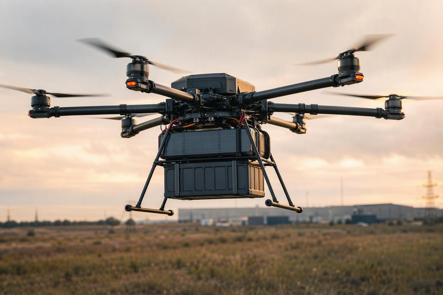
Industrial UAVs must deliver sufficient power for takeoff, climb, hovering and payload operations. Once the required power is established, battery voltage becomes an important design variable because it determines the current needed to deliver that power.
That is why the current a design must carry is often far higher than buyers expect. The harness, connectors and busbars that feed the propulsion stack have to be sized for the high-current case. Every extra amp of capacity then adds conductor mass. Working within a lower current envelope may allow lighter wiring and connectors, which creates opportunities to reduce aircraft mass or preserve payload budget. That trade-off is exactly what pushes industrial platforms toward higher voltage in the first place.
Current also drives heat, and heat is a reliability problem as much as an efficiency one. At high current, the harness, connectors and ESC input can build up heat quickly, which speeds up insulation ageing and terminal oxidation and, in the worst case, can lead to thermal failure or an in-flight power cut. Lowering the current lowers that heat load, which keeps the power path cooler and eases the cooling requirement. For long-endurance industrial missions, that margin can matter more than the raw efficiency gain.
How Does Higher Voltage Reduce Current and Wiring Losses?
At a fixed power level, doubling voltage halves current. Because resistive loss follows the square of current, this reduces the loss to one-quarter in a path with unchanged resistance. The same principle applies to the cabling and connectors in an industrial UAV power system.
Put plainly for a procurement reader: the loss is not a straight line. A 50% current reduction removes 75% of the loss, not 50%. The loss follows P_loss = I² × R. That means both the current and the resistance in the path matter equally.
A quick example makes the effect concrete. Take a 100 kW load: at 200 V it draws 500 A, and at 400 V it draws 250 A. Hold the path resistance at a fixed 20 mΩ, and that halved current cuts the loss from 5,000 W to 1,250 W — a 75% drop.
Two points keep the example honest. The 20 mΩ resistance and the 100 kW load are illustrative assumptions, not measured values or typical multirotor figures. And the math covers resistive loss in one fixed-resistance path, not total propulsion efficiency, which also depends on the ESC, the motor and how the aircraft is flown. Still, the relationship it shows is the one that matters — and it applies to the cabling and connectors first, not to the cells.
Does Higher Voltage Reduce Battery Internal Losses?
Here is the distinction that trips up most buyers. Raising voltage cuts the current in the external path — cables, connectors and busbars. It does not automatically reduce the battery’s internal resistance or make its cells more efficient. Cell-level losses depend on the cells’ resistance and operating conditions. Total pack losses also depend on the series-parallel configuration, interconnections and current distribution. A higher-voltage design can reduce current in parts of the system, but its effect on internal losses has to be assessed at pack level.nnWhen current flows through cell resistance, the cell heats up, voltage drops under load, and the protection cuts off early, leaving energy behind. That early cutoff is how nameplate energy becomes unusable.
The voltage drop inside the pack follows Vdrop = I × R, so it grows with current and can trigger premature low-battery warnings or failsafe. This is the same mechanism behind the in-flight voltage sag that undermines industrial fleet reliability, and it is why a pack can look fine on a bench and still fall short under load. Higher voltage lowers the current that produces that drop, which helps, but it does not lower the cell’s own resistance — and a pack that looks clean on paper can still brown out in flight if a connector or a weld is the weak link.
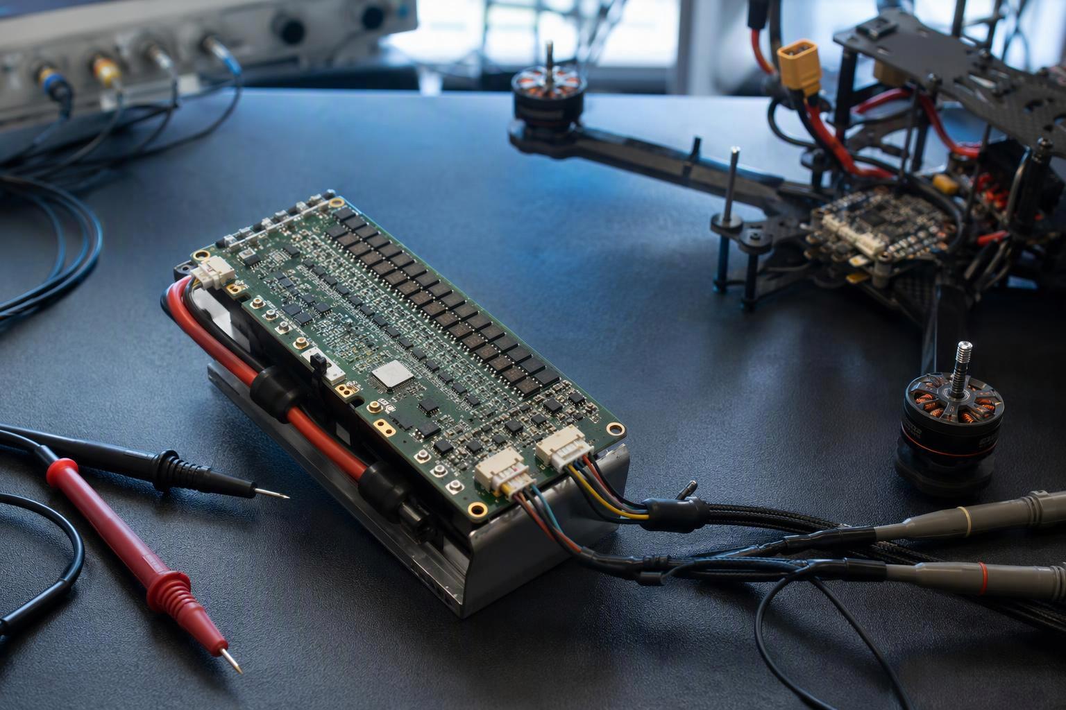
This is why raw milliohm figures are not comparable across cells unless the test method is the same. Internal resistance shifts with temperature, state of charge, measurement frequency and cell model. A single number pulled from a datasheet is therefore easy to misuse. Ask for DCIR (direct-current internal resistance) measurements taken under defined conditions, and compare packs using the same test method, temperature and state of charge.nnFor the same reason, a cell datasheet is not a pack specification. Cell-level gains do not translate upward automatically, so pack-level resistance and loaded voltage behavior have to be verified on the assembled pack.
The key distinction is that higher voltage can reduce current in parts of the power system, lowering wiring losses and potentially reducing current-related voltage sag. Its effect on battery-pack losses depends on the cell configuration, interconnections and operating conditions; it does not automatically improve cell-level efficiency.
What Are the Trade-Offs of a Higher-Voltage UAV System?
Higher voltage does not remove the need to re-match the ESC, the motor, the insulation and the cost structure. It moves the difficulty to those places, and a buyer who only compares cell count will miss them. This is the same trade-off that governs how payload capacity is set by battery power and weight on the airframe.
The ESC sets a hard limit first. The ESC’s specified operating range must cover the battery pack’s voltage range, including its fully charged voltage, with appropriate margin for the system design. Compatibility should be checked against the ESC manufacturer’s voltage limits, not the pack’s nominal voltage alone (T-Motor). An ESC that will not even start below its minimum bus voltage is a hard constraint rather than a preference.
Component availability varies by voltage class, motor and ESC platform, and supplier, so what can be sourced off the shelf at one voltage may need a purpose-built high-voltage ESC and motor at another.
The motor has to be re-matched too. Kv is the no-load speed constant per volt (RPM = Kv × V), so a motor’s RPM rises in proportion to pack voltage. Low Kv pairs with large props and high Kv with small props. Raise the voltage without re-matching Kv, and the propulsion system may land outside its efficient range, even though the current is lower.
Higher voltage also increases insulation and clearance requirements and may introduce additional BMS and compliance considerations, depending on the system architecture and applicable standards — and those changes cost board area and weight.
Cost is where the evidence runs out. Lower current lets current-carrying parts stay smaller and lighter — cables, connectors, motors and cordsets. Less heat also means cooling can be less demanding. Whether that nets out cheaper depends on the added insulation, device and BMS costs, so treat cost as a qualitative trade rather than a number.nnThis is also why there is no value in raising voltage beyond what the mission needs. Once the current reduction is no longer buying a lighter or cooler power path, the added insulation and component requirements only add cost and mass.
How Do You Choose the Right Battery Voltage?
Fix power first. Then estimate current across the expected operating voltage range, including the lowest voltage under load. Confirm that the battery, wiring and power electronics can carry the resulting current. Only then does voltage selection make sense, because the highest current demand comes at the lowest operating voltage, not at nominal. The checklist below turns that into a repeatable sequence.
Step | Action | What to check |
|---|---|---|
1 | Define the mission power requirement | Takeoff and climb power, not just cruise average |
2 | Estimate current across the operating voltage range | I = P / V, especially at the lowest voltage under load |
3 | Estimate wiring losses | P_loss = I²R across the relevant current path |
4 | Check ESC voltage compatibility | Confirm the specified operating range covers the pack’s full-charge voltage |
5 | Match the motor and propeller | Verify Kv, RPM, thrust and operating efficiency |
6 | Verify the assembled battery pack | Check pack weight, energy, output capability and resistance measurements under defined test conditions |
Pack voltage by cell count is the practical starting point for step 2. A 6S pack is 22.2 V nominal and 25.2 V full, 8S is 29.6 V and 33.6 V, 12S is 44.4 V and 50.4 V, and 14S is 51.8 V and 58.8 V. Above that, 18S and 24S packs are used on larger heavy-lift and long-endurance platforms where the mission power requirement is higher still. What 12S means at the terminals is a 44.4 V nominal pack that reaches 50.4 V at full charge, and that full-charge figure is the number the ESC must survive.
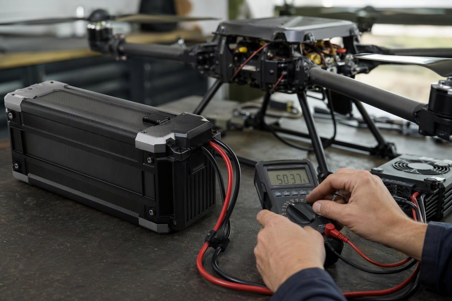
The verification half is where most projects lose time. Cell-level figures alone cannot establish pack performance. Ask for assembled-pack data under defined test conditions, including loaded voltage, output capability and resistance measurements appropriate to the application. For a specific project, the real test is whether the supplier can show the pack meets the performance and safety margins you set, not whether it delivers one particular format of data.
الأسئلة الشائعة
Why does higher voltage reduce current?
Because power is the product of voltage and current (P = V × I), so at constant power raising voltage lowers current in inverse proportion. Doubling the voltage halves the current for the same power, and because resistive loss scales with the square of the current, the loss in the wiring falls even faster than the voltage step.
Does a higher-voltage battery always improve UAV performance?
No. Higher voltage lowers the current in the external path and reduces wiring loss, but it does not raise the cells’ internal efficiency, pack energy density or flight time. It also forces a re-match of the ESC, motor Kv and insulation, and the ESC’s maximum voltage must still exceed the pack’s fully charged voltage.
What should I check when selecting an industrial UAV battery?
Start from the mission power requirement, estimate current at the lowest voltage under load, and compute the loss across the full path. Then verify the ESC against the pack’s full-charge voltage, re-match Kv, and ask the supplier for pack-level weight, energy, output capability and DCIR distributions measured under defined test conditions.
Higher Voltage Is a Trade, Not a Guarantee
Higher voltage can reduce current and wiring losses in a high-power UAV system, but it does not automatically improve battery efficiency, pack energy density or flight time. The right voltage has to be selected and validated against the aircraft’s power demand, the battery’s characteristics and the propulsion system’s limits.
Take the checklist to your own project: fix the power, estimate current at the lowest voltage under load, then verify the ESC, motor Kv and pack data against the numbers a supplier can actually prove. A supplier should be able to support that process with pack-level performance data and clearly defined test conditions.

 العربية
  English
  Español
  한국어
한국어  Deutsch
  Français
  日本語
日本語  Русский
  Bahasa Indonesia
  ไทย
ไทย  Português do Brasil
  Italiano
  Nederlands