
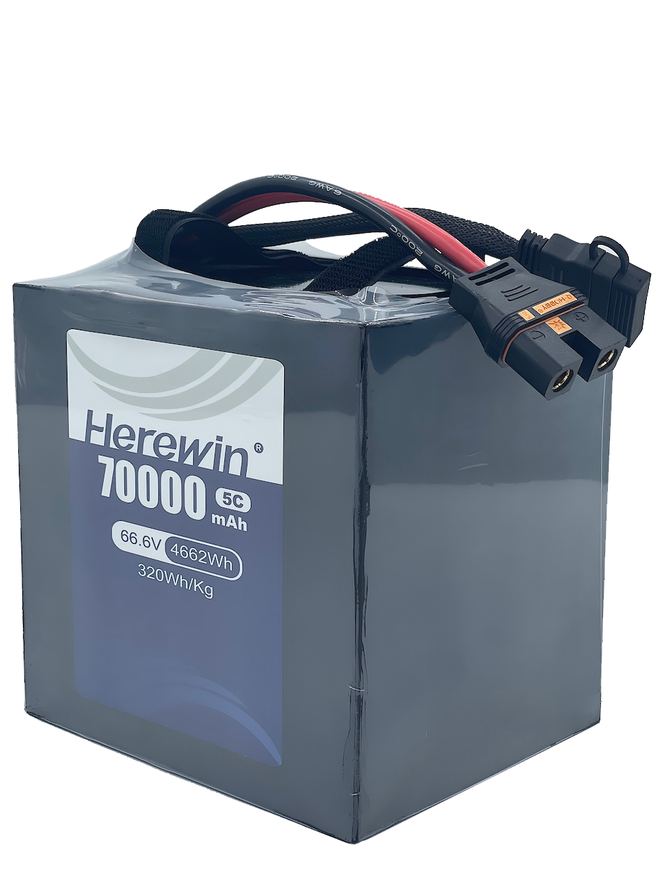





Two drone battery packs can use exactly the same cells, store exactly the same energy, and still make completely different demands on the rest of the aircraft. That’s the part of the series-versus-parallel question most design reviews get wrong.
Start with the same 12 cells and change only how they’re wired. Here S is the number of cells in series and P is the number of parallel cells per group: a 12S1P pack is one string of 12 cells, a 6S2P pack is six groups of two paralleled cells. Wire those 12 cells both ways and the cell count, chemistry and total energy come out identical — so the argument has to be settled somewhere other than the cell.
It turns out the two builds load every cell the same way. The real difference sits at the busbars, connectors, sense wiring and telemetry — and those are the parts a procurement spec can actually name.
The 12-Cell Baseline: Two Ways to Wire the Same Chemistry
Take 12 identical cells of 10 Ah and 3.7 V nominal each, and wire them two ways. In a 12S1P S/P configuration the cells sit in one series string: 44.4 V nominal, 10 Ah, 444 Wh. In a 6S2P build, six series groups each hold two cells in parallel: 22.2 V nominal, 20 Ah, 444 Wh. Same energy, same cell count, same chemistry.
Parameter | 12S1P | 6S2P |
|---|---|---|
Nominal voltage | 44.4 V | 22.2 V |
Pack capacity | 10 Ah | 20 Ah |
Pack energy | 444 Wh | 444 Wh |
Bus current at 2 kW | 45 A | 90 A |
Current per cell at 2 kW | 45 A (4.5C) | 45 A (4.5C) |
Series nodes the BMS must sense | 12 | 6 |
The per-cell current load is identical in both builds, and that is the result most configuration debates miss. At 2 kW the 12S1P pack draws 45 A through one string, so each cell carries 45 A. The 6S2P pack draws 90 A at the bus, but each parallel group splits that current between two cells, so each cell still carries 45 A. Per-cell I²R heating and per-cell electrochemical rate are the same.
The penalty lands on the system boundary instead. Doubling bus current doubles the current through every conductor, connector, fuse, PCB trace and switching device in that path, and loss in those elements scales as I²R. The 6S2P build also halves the series nodes the BMS must sense, from 12 individual taps to 6 shared group taps — the first hint that the two topologies don’t report the same information about their cells.
The Voltage Trap: Why Power Scaling Dictates Your S-Count
UAV battery pack voltage is a power-scaling decision, not a preference. For the same power demand, higher voltage means lower current, and the current is what sets conductor mass, connector rating and thermal overhead. The arithmetic is I = P/V, and it produces a steep ladder across the voltage classes a commercial UAV actually uses.
Power class | 22.2 V (6S) | 44.4 V (12S) | 51.8 V (14S) |
|---|---|---|---|
2 kW | 90 A | 45 A | 39 A |
5 kW | 225 A | 113 A | 97 A |
10 kW | 450 A | 225 A | 193 A |
20 kW | 900 A | 450 A | 386 A |
The table is computed from I = P/V at the nominal voltages of the 6S, 12S and 14S classes. At 22.2 V, a 2 kW load already draws 90 A, which is the point where connector contact resistance and harness gauge stop being details. C-rating is the other half of that picture: it is what tells you whether the cells you picked can actually deliver the current the pack now has to carry. The same 2 kW at 44.4 V draws 45 A. A 10 kW agricultural spray load at 22.2 V draws 450 A; at 51.8 V it draws 193 A.
Power vs. Current Scaling (I2R Losses)
The I²R loss battery harness calculation is where the voltage choice becomes a mass and thermal decision. At fixed conductor length, material and cross-section, resistance is constant, so doubling current makes I²R heating four times larger and doubles voltage drop. Holding the original dissipation requires roughly 4x the copper cross-section and about 4x the copper mass in that path, a 300% increase in conductor mass. The fourfold rule is the whole argument: at a given power, doubling the current makes resistive loss four times higher in every element of that path unless the copper grows to match.
Getting this wrong has a measurable consequence, and it shows up in how parallel cells actually share current. Real busbars have finite resistance, so parallel cells sit at slightly different local potentials and the cells nearest the current feed carry more than their share. The imbalance grows with busbar resistance and with charge rate, and a pack-level voltage reading can hide it (Marco et al., IEEE Transactions on Transportation Electrification, 2022).
Decoding Industrial Voltage Labeling
The ESC voltage rating LiHV question is the most common procurement error in this section, and it comes from reading the nominal label instead of the charged ceiling. Standard LiPo is 3.7 V nominal and 4.2 V full per cell; LiHV is 3.8 V nominal and 4.35 V full. A 6S standard LiPo is 22.2 V nominal but 25.2 V fully charged, and a 6S LiHV is 22.8 V nominal but 26.1 V fully charged. The same audit applies up the ladder: a 12S standard LiPo is 44.4 V nominal but 50.4 V fully charged, and a 12S LiHV is 45.6 V nominal but 52.2 V fully charged. A voltage-sensitive part must be checked against the fully charged ceiling, not the nominal label.
Manufactured platforms show the same distinction at scale. The Agras T10’s 14S, 51.8 V battery is rated 9,500 mAh at about 3.8 kg with an 11.5C discharge rate and IP54, and the aircraft’s maximum operating voltage is stated as 60.9 V for a 14S LiPo (DJI Agras T10 specifications). The 51.8 V figure is the nominal class; 60.9 V is the ceiling the airframe is built around. Raising the S-count lowers bus current and conductor mass, but it also raises the charged ceiling that every ESC, connector and insulation system must survive.
The 1P Architecture: Large-Format Pouch Cells & Trade-Offs
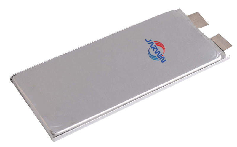
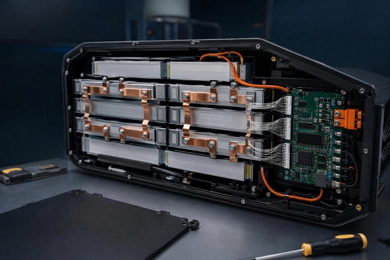
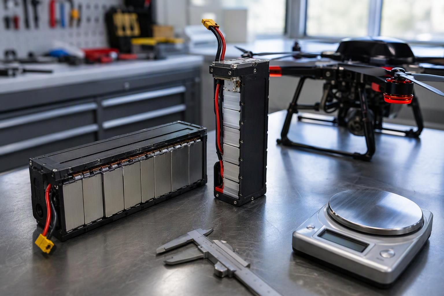
Large-format pouch cells make a 1P architecture practical for UAV packs where weight, volume and serviceability matter. A 1P build replaces each parallel group with a single cell, so every cell gets a dedicated tap to the BMS. That removes the parallel balancing blind spot before it appears, and it simplifies the mechanical layout: fewer cells and joints mean fewer interconnects, welds, sense wires and fixtures, and the busbar welding stack that vibration-prone airframes have to survive gets smaller. Large pouch cells also bring better volumetric efficiency and a direct tab path for thermal management.
The trade-off is that a pure 1P configuration concentrates more energy into each cell, and the pack’s usable capacity then collapses to its weakest cell. If one pouch cell suffers severe degradation or a sudden voltage drop mid-flight, a single weak cell narrows the pack’s usable voltage margin, so reliability shifts onto rigorous factory-level cell matching rather than parallel redundancy.
The parallel-small-cell alternative moves the complexity rather than removing it. Current distribution, balancing strategy and fault isolation all get harder, connection points multiply, resistance can drift under vibration, and QA steps increase. It buys redundancy of current path at the price of per-group telemetry. Any parallel design then requires per-cell voltage and temperature visibility at least at the series-group level, and meaningful per-group telemetry to make that data useful.
The result is a channel-count trade. A 12S1P pack needs 12 sense channels and no group-averaging logic. A 6S2P pack needs 6 channels but each channel reads a group, and the group reading is where the next section’s problem begins.
BMS Sampling Blind Spots in Parallel Topologies
BMS parallel balancing has a structural limit that no firmware update removes: a balance lead reads the averaged potential of the cells it is connected to, not the individual cells. A sense lead measures potential between electrical nodes, and permanently paralleled cells are one node pair, so one tap reads the group terminal voltage. A high-impedance sense conductor carries negligible current and therefore carries no information about how group current divides (Smart Battery Data Specification v1.1).
The same limit shows up in the standard telemetry vocabulary. Both the Smart Battery Data Specification and DroneCAN’s standard data types report one set of pack-level values — voltage, current, temperature, state of charge — rather than one set per parallel branch.
Branch currents are set by each cell’s internal impedance plus its interconnect path resistance. Differences in resistance, temperature, SoC, aging and weld quality all shift the split, while the reported group voltage stays normal. Parallel modules have shown cells nearer the terminals carrying close to twice the average current at 1C, feeding uneven aging (Ayalasomayajula et al., J. Electrochem. Soc. 172, 080526). Detecting that split needs branch-current sensing, extra temperature sensing, or physically separate cells.
A parallel topology can therefore pass every pack-level check while one cell in a group works harder than its neighbour. That gap is what makes parallel groups the harder reliability case, and it is why the compensating control has to come from cell matching rather than telemetry. If you want to know what a BMS can and cannot see on the wire, the protocol layer is where that limit is actually written down.
That is why parallel designs depend on tight factory-level matching as the compensating control. Because the BMS cannot see inside a group, the sorting tolerances have to do the work the telemetry cannot, so that current divides evenly at the start and stays even as the cells age. There is no universal matching figure to quote here — it depends on chemistry, cell format, state of charge, test temperature and measurement method — so a workable spec states it as an agreed criterion between buyer and supplier for the specific design. A 1P large-format layout sidesteps the problem entirely, because dedicated balance leads give the BMS direct visibility into every cell stage, which is the same reason parallel groups are the harder reliability case.
Field Realities: Pack-Level Parallelism (12S2P)
A 12S2P pack parallel arrangement at the aircraft level is a different problem from parallelism inside a pack. Connect two packs and you’ve created an equalization event before any charger or load is involved: the packs trade current until their voltages match. Because total resistance is low — pack resistance plus wiring — even a modest voltage difference produces a large transient. The practical rule is to parallel only packs with equal cell counts, and only within about 0.1 V per cell, ideally 0.05 V or less. That number is field convention rather than a standard, but the mechanism is the same I = ΔV/R physics that governs everything else here.
The verification step is a pre-connection open-circuit voltage check on every pack, with the measured values recorded and the delta held inside the tolerance before the connectors touch. A pack that has been sitting at a different state of charge, or one that has just come off a partial charge, is the case that produces the transient. Smart packs add a second line of defence with BMS pre-charge circuits and integrated anti-spark logic that limit the inrush when the connectors mate, but those circuits assume the OCV check was done, not that it can be skipped.
Charging is the second field-level blind spot. A pack that is paralleled at the aircraft but charged as a single unit hides the same group-level divergence the BMS cannot see, and the diagnostic path for a capacity shortfall runs through the same pack-level data. Field parallelism multiplies the number of equalization events a fleet sees, and each one is a chance for a mismatched pack to take more than its share of the transient.
Selection Logic: Five Steps for System Architects
Think of this as a checklist you run before a supplier conversation. Each question produces a number or a spec line.
What voltage does the aircraft allow? Start from the charged ceiling, not the nominal label. A 14S standard LiPo is 51.8 V nominal and 60.9 V fully charged, and LiHV pushes the ceiling to 4.35 V per cell instead of 4.2 V.
What power does the propulsion system demand? Take peak and average power from the propulsion model, not a nameplate.
What current does that create? Divide power by voltage: 2 kW is 90 A at 22.2 V, 45 A at 44.4 V and 39 A at 51.8 V.
Can the physical and thermal design carry it? Holding dissipation at doubled current needs roughly 4x the copper cross-section, so a 6S build pays for its convenience in busbar and harness weight.
What cell-level visibility does the BMS need? Pack-level voltage and current are the default in both the Smart Battery data set and the DroneCAN battery message; per-branch current requires branch-current sensing or separate cells. Write that requirement, the cell-matching tolerance and the OCV alignment rule into the purchase spec.
Steps 1 through 4 produce the configuration and step 5 produces the contract. A supplier can meet a voltage and capacity requirement and still fail the spec if the matching tolerance and telemetry granularity were never written down. Then name which compliance regime applies and for what. UN 38.3 governs transport and does not certify operation in an aircraft. IEC 62133-2:2017 covers portable sealed lithium cells and batteries. UL 2580 addresses electric-vehicle energy storage assemblies, not performance or reliability.
Custom Configuration Engineering
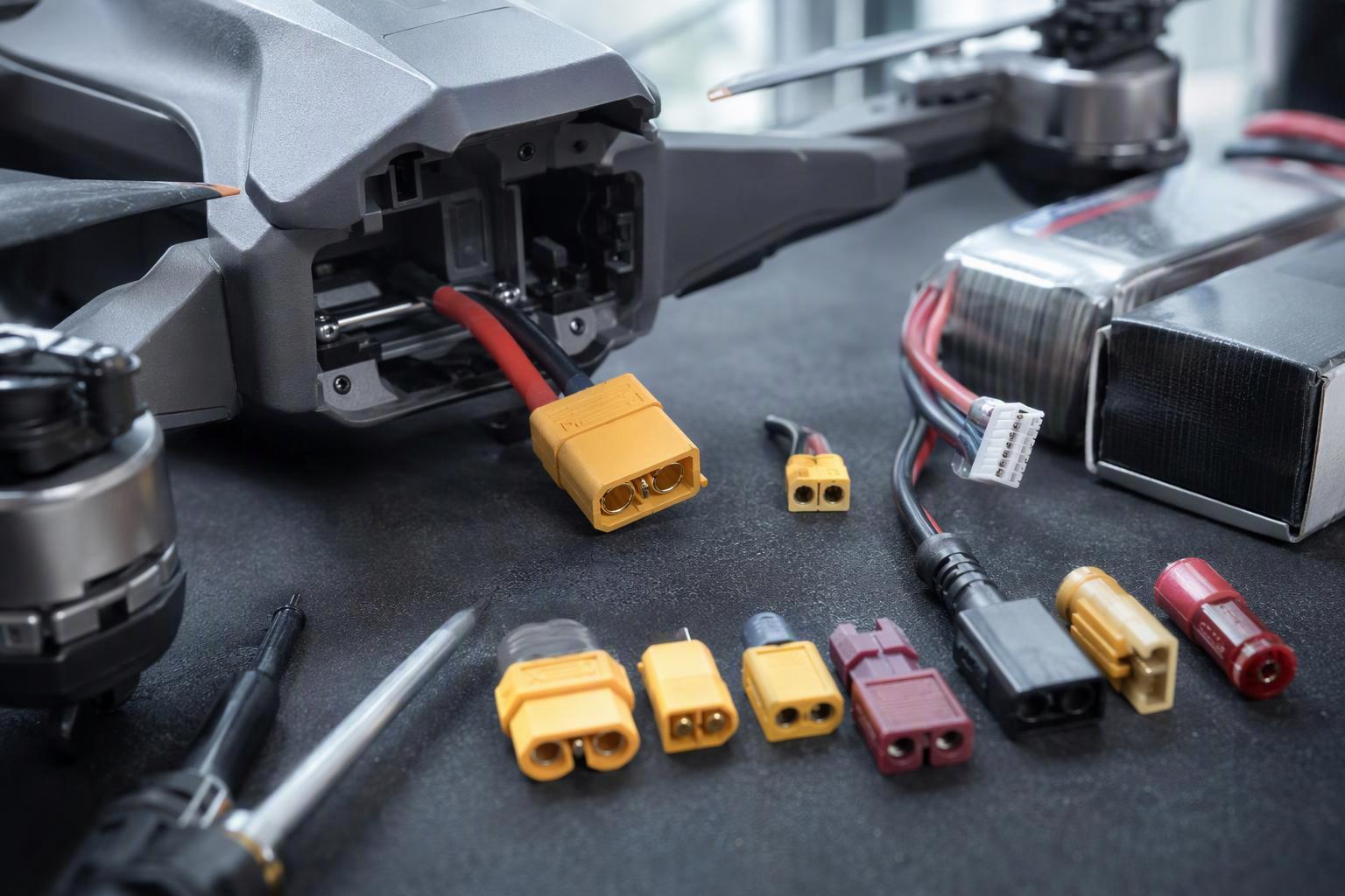
Custom configuration work starts from the parameters that are expensive to change later. Lock down the mechanical envelope first — battery bay dimensions and tolerances, mounting, ingress boundaries, the maximum battery mass, and the centre-of-gravity position with its allowable variation band. Then settle the connector: interface model, current-carrying capacity, voltage rating, keying, vibration rating, ingress protection and mating-cycle life. Fix these at project start rather than discovering them during integration, because they are the changes that ripple through everything else.
Cell rate is a static parameter; pack dynamic rate is what the mission actually sees. A pack matched to the mission current profile is what protects production endurance, so the sorting criteria should cover capacity, internal resistance, voltage plateau, self-discharge and temperature characteristics — not capacity alone. Those are the same parameters that belong in a custom PACK specification before tooling is committed. Match wire gauge to maximum mission current, and quantify internal and contact resistance as an ex-factory inspection item.
That leaves three points worth putting in front of a supplier: the charged-ceiling rating of every ESC and connector, the matching tolerance for parallel groups, and the pre-connection OCV alignment rule for field-parallel packs. Those are the questions we at Herewin ask first when reviewing a custom UAV battery architecture. If you’re weighing a 12S1P against a 6S2P build for an airframe that’s already flying, send us your ESC voltage limit, power profile and mission duration, and we’ll help you settle the configuration before it reaches the purchase spec.
الأسئلة الشائعة
Does a 6S2P pack put more stress on its cells than a 12S1P pack?
No. At equal pack power, per-cell current, I²R heating and electrochemical rate are identical in both builds, because a 6S2P pack’s doubled bus current is split between two cells per group. The penalty lands on the conductors, connectors and switching devices in the bus path, where loss scales as I²R.
Can a BMS detect one weak cell inside a parallel group?
Not through a conventional balance lead. Permanently paralleled cells are a single node pair, so one tap reads the group voltage and says nothing about how the current divides. Detecting a split needs branch-current sensing, extra temperature sensing or physically separate cells.
What voltage should I check my ESC against?
The fully charged ceiling, not the nominal label. Standard LiPo is 3.7 V nominal and 4.2 V full per cell, so a 14S pack is 51.8 V nominal and 60.9 V fully charged. LiHV raises the ceiling further at 4.35 V per cell, so a 6S LiHV pack is 22.8 V nominal but 26.1 V fully charged.
How closely must two packs match before I parallel them in the field?
Equal cell counts, and within roughly 0.1 V per cell — preferably 0.05 V or less. Connecting two packs is an equalization event before any charger or load control, and because total resistance is low, a modest voltage difference produces a large transient current.
Which compliance standard applies to a UAV battery pack?
It depends on the purpose, and the spec should name which one applies and for what. UN 38.3 governs transport and does not certify operation in an aircraft. IEC 62133-2:2017 with Amendment 1 covers portable sealed lithium cells and batteries. UL 2580 addresses electric-vehicle energy storage assemblies, not performance or reliability.



 العربية
 English
 Español
 한국어
 Deutsch
 Français
 日本語
 Русский
 Bahasa Indonesia
 ไทย
 Português do Brasil
 Italiano
 Nederlands