


Heavy-lift UAV fleets don’t fail because a datasheet looked bad. They fail when pack behavior becomes non-deterministic: one aircraft returns early, another runs hot on the same route, a third hits undervoltage protection at a SOC that “should have been fine.”
In heavy-lift operations, battery quality isn’t a single number—it’s a distribution. This guide shows how to control that distribution from day one: incoming screening, batch compatibility, and retirement rules that prevent surprises.
Written for heavy-lift UAV technical procurement and reliability teams, the goal is simple: predictable dispatch, simpler maintenance, and supplier stability you can scale.
Why Battery Cell Acceptance Matters in Heavy-Lift UAV Operations
Why heavy-lift UAV missions amplify battery inconsistency risks
Heavy-lift duty cycles push batteries into the corner cases where inconsistency shows up fast:
High peak current segments (takeoff, climb, recovery) turn small resistance differences into large voltage-sag differences.
Thermal stress rises with load (I²R losses), so mismatch becomes a heat-imbalance problem—not just a runtime problem.
Tight dispatch windows punish any pack that needs extra cooling time, extra balancing time, or unplanned swaps.
In other words: what looks like “normal variation” at low load becomes a fleet reliability issue at heavy load.
How weak cell consistency affects flight reliability, thermal stability, and mission uptime
In a multi-cell series string, the “weakest” cell tends to set hard limits:
Undervoltage trips happen earlier because one cell sags first.
Imbalance grows because cells diverge in self-discharge and impedance.
Thermal hotspots appear because higher-impedance cells run hotter at the same current.
The operational symptom is simple: you lose predictability—and predictability is what you schedule around.
The hidden operational cost of unstable battery quality across fleets
Unstable battery quality rarely shows up as a single catastrophic event. It shows up as:
more aborted missions
more pack rotation complexity
more troubleshooting time chasing “airframe problems” that are actually power behavior
higher spare inventory (because you can’t trust any pack to behave like any other)
Your acceptance workflow is not “incoming QA.” It’s fleet uptime insurance.
Why Traditional Battery Acceptance Methods Often Fail in Heavy-Lift UAV Fleets
Why “passing the datasheet” does not guarantee operational reliability
Datasheets are necessary—but they’re not mission-specific. They usually don’t answer the questions heavy-lift fleets actually live with:
What does voltage sag look like at your current profile?
How consistent is that sag pack-to-pack and batch-to-batch?
How does behavior shift with temperature, humidity, and aging?
Even when certifications are present, they often prove the wrong thing. For example, UN 38.3 is primarily a transport qualification (shipping safety), not a promise of lifecycle reliability in your duty cycle (see the UN’s own Manual of Tests and Criteria, Section 38.3).
The five reliability dimensions behind UAV battery system stability
For heavy-lift fleet reliability, you care about a set of linked dimensions:
Energy consistency (capacity + usable capacity window)
Power-path consistency (internal resistance + connectors + harness quality)
Thermal consistency (temperature rise under standardized load)
Aging consistency (how fast SOH/RUL diverges across packs)
Control consistency (BMS behavior, protections, telemetry quality)
A method that checks only one dimension will miss the failure mode that actually causes downtime.
You’ll sometimes hear the same idea described in slightly different “five levers” language—cell consistency, SOH/RUL, fault diagnosis, communication compatibility, and system-level reliability. Practically, those map back to the list above:
Cell consistency → energy + power-path + thermal consistency
SOH/RUL → aging consistency
Fault diagnosis + communication compatibility → control consistency (BMS behavior, protections, telemetry, and data quality)
System-level reliability → the outcome you’re trying to stabilize across the fleet
In practice, these levers form a lifecycle workflow—screen cells on arrival, control lot-to-lot compatibility, keep traceability tight, and retire predictably.
The rest of this guide breaks that lifecycle workflow into an actionable structure you can run in procurement, incoming QA, and fleet maintenance.
Why Heavy-Lift UAV Fleets Need Lifecycle-Level Battery Validation
Incoming acceptance is necessary—but it’s not sufficient. Heavy-lift fleets need a workflow that:
rejects outliers early,
prevents batch drift from silently contaminating the fleet,
and retires cells predictably before aging turns into mission instability.
Those goals map directly to the stages in this guide: Stage 1 screens incoming cells for consistency, Stage 2 controls lot-to-lot drift and cross-batch mixing, and Stage 3 sets retirement thresholds before aging becomes a mission risk.
Stage 1 — UAV Battery Cell Acceptance Testing: Incoming Cell Consistency Screening
In heavy-lift programs, incoming inspection is not just “does it meet spec?” It’s whether the cells are consistent enough to make pack behavior predictable under your duty cycle.
What “cell consistency” really means in multi-cell UAV battery packs
“Consistent” does not mean “all cells look similar at rest.” It means cells behave similarly under the same electrical and thermal stress.
At minimum, consistency should cover:
OCV alignment (proxy for initial SOC alignment when measurement is controlled)
Capacity alignment (energy)
Resistance/impedance alignment (power + heat)
Self-discharge alignment (balance drift)
Dynamic response alignment (sag + recovery fingerprint)
In heavy-lift packs, resistance mismatch often creates more mission risk than small capacity mismatch—because it drives sag, heat, and early cutoffs.
Static parameter screening: capacity, OCV, DCR, and self-discharge
A practical incoming gate typically starts with fast measurements on every cell, then escalates based on criticality.
A widely used baseline is 100% incoming inspection on OCV and ACIR, with additional 100% checks (DCIR, capacity, self-discharge) if those parameters are critical to the application—at least until supplier stability is proven. Electronic Design summarized this well in a Keysight-informed discussion of battery-cell testing for incoming inspection, including a practical rule: start with “a little too much” inspection, then roll it back once the supplier’s performance is demonstrated.
How much testing is “enough” for lot release? Use a decision rule that matches operational risk:
If you have a stable, proven supplier and your missions run with healthy voltage margin, OCV + ACIR can be a practical high-throughput screen.
If your fleet is sag-limited, sees hot returns, or you’re onboarding a new lot/supplier/process change, add DCIR (pulse), a capacity verification step, and a dynamic signature segment to prevent “in-spec” cells from producing non-interchangeable packs.
If you’ve seen imbalance growth or unexplained storage drift, add a self-discharge screen because it directly drives balancing downtime and early pack derates.
What to control (non-negotiable):
temperature during measurement
rest time before OCV reading
fixture/contact resistance (especially for IR)
method definition (pulse profile for DCIR, frequency for ACIR)
calibration and measurement uncertainty
If you don’t control these, you’ll get false pass/fail calls and unstable matching. If your incoming results don’t correlate with the supplier’s numbers, fix the metrology first.
Operational Meaning
Tighter Stage 1 matching reduces swaps, balancing holds, and return-voltage scatter—making dispatch planning more predictable.
Dynamic consistency testing using voltage recovery behavior
Static screens catch many issues, but heavy-lift operations expose dynamic mismatch.
A practical dynamic screen is to look at the cell’s voltage behavior during and after a standardized load pulse:
loaded minimum voltage (sag under a defined current)
voltage recovery after pulse removal (rebound/relaxation)
recovery rate (how quickly it returns toward equilibrium)
Why it matters: two cells can look similar at rest and still behave very differently under load. Your pack doesn’t fly at rest.
Recommended acceptance thresholds for heavy-lift UAV applications
There is no universal “good” threshold that applies across cell formats, chemistries, and mission profiles. A defensible way to define acceptance thresholds is:
Define a standardized load segment (current, duration, ambient conditions) that reflects your worst-case mission moment.
Measure cell distributions for: OCV, IR, capacity, self-discharge, and dynamic sag/recovery.
Set limits based on:
allowable sag margin before undervoltage protections,
allowable thermal rise,
and allowable imbalance growth over your maintenance interval.
If you need a starting point, use relative thresholds (e.g., “reject outliers beyond Xσ from batch mean under controlled conditions”) rather than copying someone else’s absolute numbers.
Absolute limits without defined test conditions (temperature, SOC, pulse profile, rest time, fixtures) are not “thresholds.” They’re folklore.
Example starting points for acceptance thresholds
The numbers below are illustrative starting points only. Use them to seed your first acceptance spec, then calibrate against your cell format/chemistry, BMS limits, connector losses, mission current profile, and test conditions.
Assumptions for the example: 25°C controlled environment, consistent fixtures, defined rest time, and a standardized pulse/segment.
Metric | Example starting limit | Why it matters operationally |
|---|---|---|
Capacity spread (cells within a build group) | ≤ ±2% | Reduces runtime scatter and helps keep packs interchangeable |
OCV spread after controlled rest | ≤ ±20 mV | Prevents initial SOC mismatch that grows into balancing holds |
DCIR/DCR spread (same method/fixtures) | ≤ ±5% | Controls sag/heat divergence that drives early cutoffs |
Self-discharge indicator | investigate outliers > ~3%/month equivalent | Prevents chronic imbalance and unexpected derates |
Dynamic sag / recovery fingerprint | investigate outliers beyond a defined band | Catches “looks fine at rest” cells that behave differently under load |
Use these as starting points, then convert them into your own lot-specific distributions and “reject outliers” rules once you have enough data.
Stage 2 — Batch Variation Control and Cross-Batch Compatibility
If Stage 1 protects you from bad cells, Stage 2 protects you from good cells that don’t match each other across lots—one of the most common causes of fleet-wide drift.
Why cross-batch variation creates hidden reliability risks
Cross-batch mixing is a common reliability trap:
You assemble packs that are “in spec,” but the fleet becomes two populations.
One population runs hotter or sags more under the same mission segment.
Maintenance becomes chaotic because behavior isn’t consistent across inventory.
Batch drift is rarely announced. It must be detected.
Operational Meaning
Controlling batch drift keeps inventory interchangeable and fleet telemetry comparable—so dispatch and maintenance don’t turn into exception management.
Voltage-drop-rate comparison testing between production batches
A pragmatic way to compare batches is to standardize one or two “signature segments” and compare:
minimum loaded voltage
recovery voltage after pulse removal
temperature rise at the end of the segment
cell-to-cell spread under load
This is aligned with how fleet reliability teams treat sag: measure it in a repeatable way, trend it, and use it as a procurement and maintenance signal. Herewin’s discussion of voltage sag as a fleet reliability criterion is useful as a framework for what to log and why.
From a procurement and reliability standpoint, this test becomes a lot-release and mixing decision: if a new batch shifts sag or thermal rise beyond your baseline, you don’t just “note it”—you segregate it, tighten matching rules, or block cross-batch mixing. That’s how you keep inventory interchangeable and keep your fleet telemetry baselines meaningful.
Using UN38.3, IEC/UL, and UAV battery standards in incoming QA
Standards and certifications often show up in batch discussions because teams use them as a shortcut for “compatibility.” Don’t—treat them as prerequisites, then still run your batch-to-batch signature checks.
Treat compliance evidence as a gate, not a guarantee.
UN38.3 answers: “Can it be shipped?”
IEC/UL safety standards answer: “Did a defined design pass a safety test set for a product class?”
Neither answers: “Will your fleet have predictable sag, temperature rise, and RUL under your duty cycle?”
If you operate in the US, also remember transport compliance is not optional even for “good-performing” batteries; PHMSA maintains an overview of lithium battery transport requirements on its lithium batteries guidance page.
How leading UAV teams build traceability and batch-level data systems
A mature acceptance system produces artifacts you can audit later:
cell-level ID + lot code mapping
incoming measurement dataset (OCV/IR/capacity/self-discharge + test conditions)
pack build mapping (which cells went into which serial)
firmware/BMS revision mapping
exceptions/MRB records
If you can’t answer “Which lot is causing today’s sag alarms?” within minutes, you don’t have traceability—you have spreadsheets.
Stage 3 — Defining Cell Retirement Thresholds Before Failures Happen
This stage is where acceptance becomes reliability engineering: you define battery retirement thresholds that prevent mission-disrupting behavior before it shows up as a “surprise failure.”
Why retirement management matters as much as incoming inspection
Incoming acceptance keeps defects out. Retirement management keeps aging variability from destabilizing the fleet.
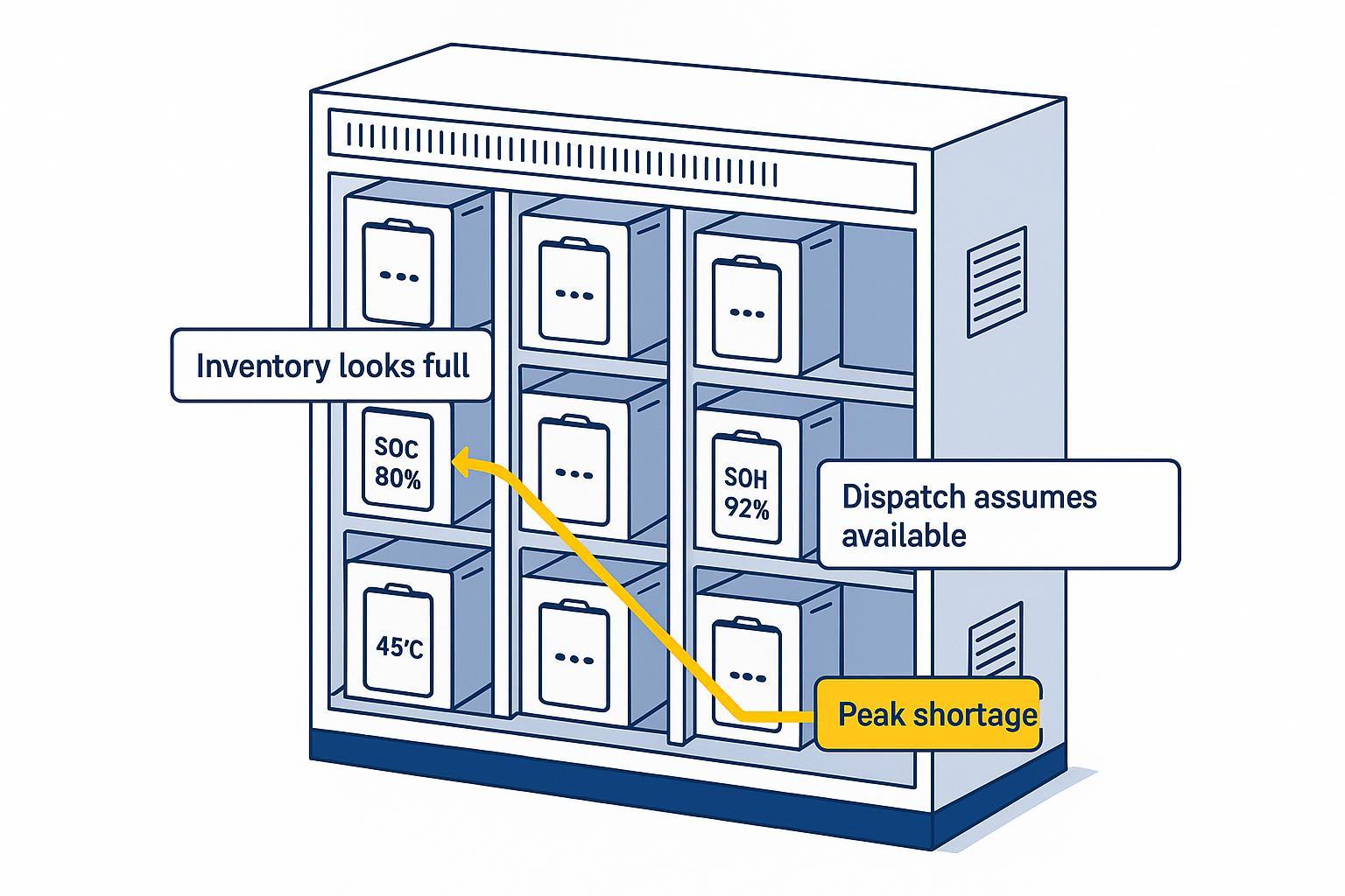
Heavy-lift fleets often discover this late: a pack can be “not failed” and still be operationally unreliable.
Operational Meaning
A retirement policy isn’t just a technical rule—it’s an operations safeguard:
Avoid surprise groundings by removing packs before sag/heat/imbalance triggers mission aborts.
Reduce emergency replacement inventory because replacements become scheduled events, not scramble purchases.
Stabilize dispatch planning: you can forecast usable inventory and mission capability instead of reacting to sudden performance drops.
Done well, retirement thresholds turn battery aging from a disruption into a manageable maintenance cadence.
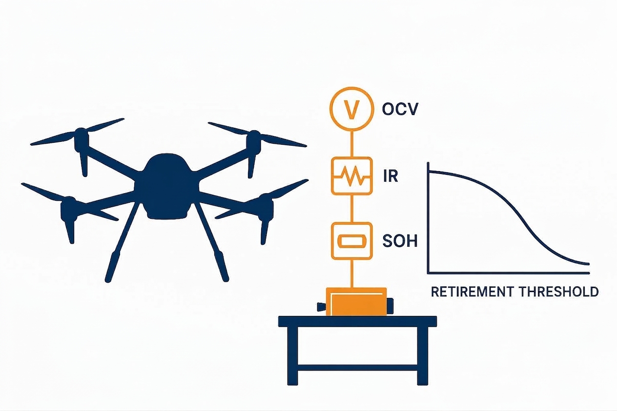
The four most important retirement indicators for UAV cells
Retirement should be multi-metric. The practical indicators that matter most in the field are:
Resistance/impedance growth (predicts sag + heat)
Voltage sag under a standardized load segment (mission determinism)
Thermal rise under comparable load (hotspot and accelerated aging risk)
Imbalance / drift (self-discharge outliers, balancing that can’t keep up)
Capacity fade matters—but in high-power missions, power capability and thermal behavior often force earlier retirement.
Operationally, these indicators are what let you move from reactive swaps to planned replacements: you can forecast which packs will become dispatch risks, keep emergency spares lower, and maintain a defensible maintenance record for internal audits and supplier discussions.
How BMS-based warning systems enable predictive retirement decisions
A BMS that supports fleet reliability should do more than protect the pack. It should help you decide when to replace it.
At minimum, you want:
per-cell voltage and temperature logs
loaded minimum voltage and recovery voltage
current, SOC, SOH estimates (with method transparency)
fault taxonomy (why did it cut back / cut off?)
exportable logs (not just in-app graphs)
Use a tiered policy:
Watch: small drift; increase inspection frequency.
Derate: restrict to lighter missions or narrower SOC window.
Retire: remove before it becomes a dispatch risk.
Building a lifecycle tracking system for UAV battery fleets
If you want predictable retirement, you must log the predictors.
A practical lifecycle schema includes:
pack serial, cell lot, build date
cumulative cycles and cumulative energy throughput
standardized segment results (sag, recovery, temperature rise)
max delta between cells under load and at rest
charge behavior anomalies (balancing time, early termination)
environmental exposure notes (heat, storage conditions)
The point is not big data. It’s comparability.
How to Build a Practical UAV Battery Acceptance Workflow
Recommended incoming inspection workflow for UAV manufacturers and fleet operators
Use this as a clean, auditable flow. Keep each step atomic.
Lot intake + documentation check
Input: supplier CoA/CoC, lot codes, revision, storage/shipping conditions
Action: verify identity matches PO and design revision
Output: lot accepted into quarantine for testing
Done when: IDs and documents are consistent and stored
Conditioning and rest (controlled environment)
Input: cells in quarantine
Action: stabilize at controlled temperature; define rest time
Output: comparable measurement starting point
Done when: temperature + rest time targets are met
100% fast screens (minimum)
Input: stabilized cells
Action: measure OCV + ACIR (and temperature) with controlled fixtures
Output: pass/fail + binning dataset
Done when: dataset is complete and traceable to every cell ID
Critical screens (as required by mission)
Action: DCIR pulse test; capacity check; self-discharge screen for high-reliability lots
Output: deeper dataset and outlier identification
Done when: outliers are dispositioned and remaining cells are binned/matched
Dynamic signature segment (recommended for heavy lift)
Action: standardized load pulse/segment to capture sag + rebound behavior
Output: dynamic consistency score
Done when: batch distribution is stable and within your mission sag/thermal margin
What data should be logged during acceptance and lifecycle tracking
Log the minimum set that allows future root-cause analysis:
test protocol version (pulse profile, cutoff voltages, rest times)
ambient and cell temperature at measurement
OCV, ACIR/DCIR, capacity result, self-discharge indicator
sag/recovery metrics (loaded minimum, recovery voltage after defined rest)
operator + fixture ID + calibration status
How to separate supplier claims from verifiable engineering evidence
A simple rule: claims are not inputs. Evidence is.
Request artifacts like:
raw test logs (not only summary tables)
measurement method and uncertainty statement
batch Cpk/yield trends for key parameters
change-control history (material, process, equipment)
failure analysis capability and turnaround time
Common acceptance mistakes that create downstream field failures
Most fleet failures start with one of these process errors:
mixing batches without a compatibility test
comparing measurements taken at different temperatures/rest times
ignoring fixture/contact resistance effects in IR tests
relying on certifications as proof of field reliability
failing to log enough metadata to debug later
How to Operationalize This in Procurement and Lot Release
To keep this from becoming a “good article” that never changes fleet behavior, convert it into a small set of procurement controls:
Define a signature segment (current, duration, ambient, SOC window) that represents your worst dispatch moment, and use it as the common comparator for incoming lots.
Require a per-lot evidence pack: lot codes + serialization, raw incoming dataset (OCV/IR/capacity/self-discharge where applicable), and the exact test conditions used.
Gate cross-batch mixing: only mix lots after a compatibility check shows sag/thermal behavior stays within your operational margin.
Tie results to actions: accept, bin/match tighter, derate to lighter missions, quarantine for deeper testing, or return to supplier.
This is how technical procurement and reliability teams turn measurement into predictable dispatch and scalable supplier management.
Procurement and Supplier Evaluation Checklist for UAV Battery Cells
What procurement teams should request beyond the datasheet
Ask for evidence that reduces procurement risk and protects fleet predictability—not just documents that look complete. The right artifacts help you prevent batch drift, avoid mismatched inventory, and keep lifecycle cost and uptime forecasts credible:
lot traceability and serialization approach
incoming inspection dataset for each shipped lot
definitions of how IR is measured (ACIR vs DCIR; pulse profile)
self-discharge screening method (and whether it’s 100% or sampled)
sample aging/cycle validation aligned to your duty cycle
Questions to ask about consistency testing, aging, and cycle validation
Use questions that force methodological clarity:
Under what temperature and rest-time conditions were OCV/IR measured?
How do you control measurement uncertainty across fixtures and multiplexing?
What is your plan for correlating your lab results with ours?
What are your lot-to-lot drift signals and how are they reported?
What evidence do you have for sag/thermal behavior under high peak current segments?
How to evaluate whether a supplier can maintain long-term batch stability
You’re not only buying cells—you’re buying a process.
Evaluate:
change-control discipline
capability to provide consistent test artifacts per lot
ability to support traceability through warranty lifecycle
responsiveness and failure analysis competence
A supplier that can’t produce auditable evidence will eventually create operational surprises.
Future Trends in UAV Cell Acceptance and Reliability Management
AI-assisted SOH prediction and predictive retirement systems
AI is not a replacement for measurement discipline. The near-term value is in:
trend detection on sag/thermal/imbalance signatures
earlier anomaly detection across fleets
better RUL scheduling using consistent telemetry + standardized segments
Why telemetry-driven QA and traceability are becoming standard
The industry is moving from “incoming QA” to closed-loop reliability:
what you measure at incoming becomes the baseline
what you see in telemetry becomes the drift signal
what you decide in maintenance becomes the retirement policy
This is how you make fleets predictable at scale.
How semi-solid-state and next-generation cells may change acceptance standards
New chemistries and formats will change which indicators move first (capacity vs resistance vs hysteresis). But they won’t change the core principle:
define a duty-cycle-relevant signature test
control measurement conditions
build traceability
retire predictably
From Cell Testing to Fleet Reliability Management
Mature heavy-lift UAV battery management isn’t about chasing a single “best” number or collecting attractive standalone parameters. It’s about keeping the fleet stable at scale—batch stability, predictable lifecycle behavior, a controllable retirement cadence, and repeatable flight behavior under standardized signature segments. The direction of travel is clear: fleets will increasingly rely on telemetry, predictive maintenance, traceability, and data-driven validation. In practice, that upgrades “cell acceptance” from a one-time incoming QA task into fleet reliability infrastructure.
If you want a second set of eyes on your acceptance workflow, book a consultation to align incoming screening, batch-compatibility checks, and retirement thresholds to your actual duty cycle.
Contact us to discuss your UAV platform, peak-current segments, and the test artifacts you’ll need for auditable lot release.