


For heavy-lift UAVs, battery selection mistakes usually trace back to one pattern: teams evaluate cell-level specs, but the aircraft behaves like a power system. Under takeoff and climb, what limits mission success is rarely nameplate capacity in isolation. It’s the coupled behavior of the full power path—cells, interconnects, connectors, BMS logic, telemetry, thermal interfaces, and maintenance reality.
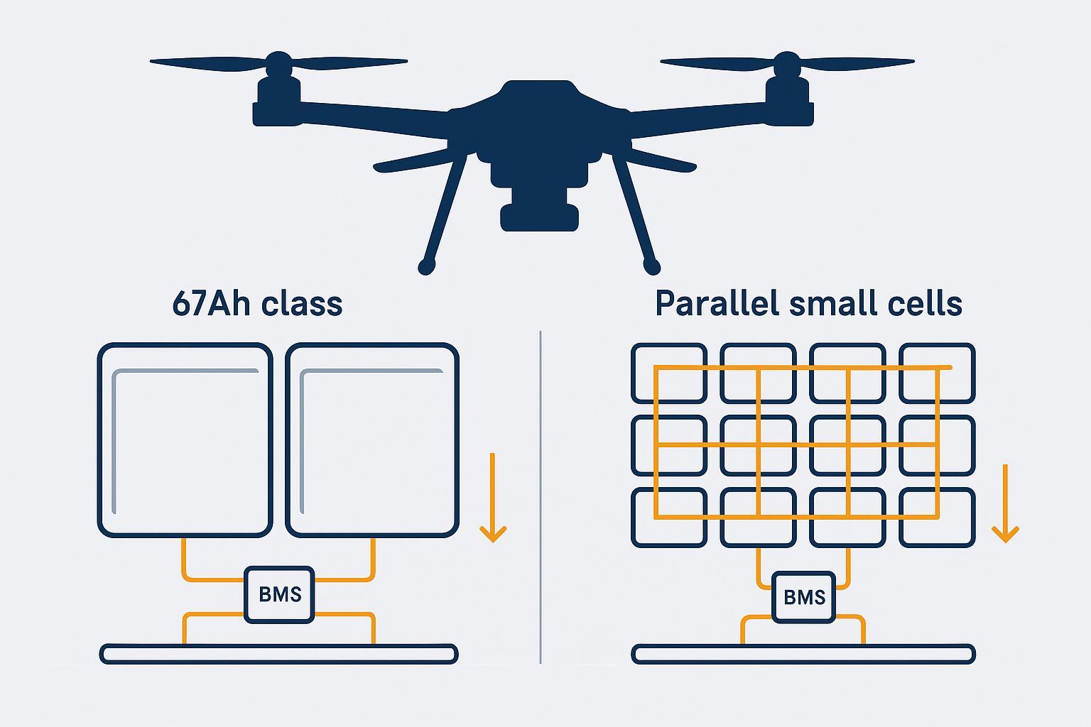
This guide focuses on a practical comparison: large pouch cell vs parallel small cells for UAV battery packs.
To keep the decision grounded, we’ll compare the two architectures across five system-level dimensions: weight and integration overhead, voltage stability under peak load, thermal gradients and hot spots, reliability and failure behavior, and maintainability in real fleet operations.
Why battery architecture is a system decision, not a component choice
Battery architecture sets boundaries for:
Voltage stability under step load (and whether the aircraft sees brownout behavior).
Thermal gradients and hot-spot risk across the pack and power electronics.
Failure behavior: abrupt mission loss vs degraded operation.
Maintainability: what you can diagnose, isolate, and retire before it becomes a fleet incident.
If you want a procurement-grade framing for voltage sag qualification (test conditions, connector effects), Herewin’s internal guide on Drone Battery Voltage Sag: Reliability Criteria for Industrial Fleets is a useful reference.
Large pouch cell vs parallel small cells for UAV battery: quick comparison matrix
Evaluation criterion | Large-format pouch (e.g., 67Ah class) | Parallel small-cell architecture |
|---|---|---|
Integration efficiency | Fewer cells and joints; fewer electrical nodes to manage | Higher node count; more harnessing and joints to validate |
Voltage sag sensitivity | Often benefits from fewer connection losses; still depends on busbar/tab design | Current sharing can be uneven; weak nodes can dominate sag behavior |
Thermal behavior | Fewer, larger heat sources; gradients can concentrate if cooling/contact is uneven | Heat can be distributed, but localized connector/busbar hot spots can dominate |
Failure consequences | Fewer parts, but each cell carries a larger consequence domain | Potential for graceful degradation if faults are isolated effectively |
BMS / telemetry complexity | Fewer series elements to monitor; simpler channel count | More complexity around current distribution, balancing strategy, and fault isolation |
Serviceability | Often “swap module/pack” oriented | Can be modular, but only if the design supports fast diagnostics + safe isolation |
In heavy-lift UAV programs, the better architecture is usually the one that delivers the most predictable voltage + temperature behavior under your worst-case segment—with evidence you can audit.
Which architecture fits which heavy-lift mission profile?
Use this as a starting map—not as a universal verdict.
Choose large-format pouch architecture when…
You’re optimizing for integration efficiency and want to minimize pack overhead.
Your mechanical design can provide stable compression/support and environmental protection.
You can demonstrate repeatability across lots using the same worst-case segment test method.
Choose parallel small-cell architecture when…
Your mission demands fault tolerance and degraded-operation capability.
Your maintenance model benefits from modular replacement and high diagnostic granularity.
You have the manufacturing maturity to control mismatch, current distribution, and isolation behavior.
Consider a hybrid approach when…
Some high-end systems blend energy density and redundancy by using a small number of medium/large elements plus deliberate isolation hardware. The point isn’t the exact topology—it’s whether the topology can be validated as a stable control system.
Core requirements of heavy-lift UAV power systems
If you only do one thing before procurement, do this: define a short, repeatable mission segment that represents the highest system stress, then compare architectures using logged evidence.
Most heavy-lift platforms converge on the same constraints:
High peak current during takeoff and climb
Battery systems see step loads, transient spikes, and sustained high discharge during climb and aggressive maneuvering.
Stable thermal performance under continuous load
Thermal behavior is rarely uniform. The risk is localized heating in cells, interconnects, connectors, or switching elements.
Safety-critical failure tolerance
In many heavy-lift missions, power loss is not a minor inconvenience. The architecture must define what “safe failure” means and how it is achieved.
Battery weight as a major system constraint
Battery weight is both payload penalty and thermal penalty (more mass can mean more energy, but also more heat to manage and more structure to support).
Define your worst-case segment before you pick a cell architecture
Define a short, repeatable mission segment that represents the highest system stress. For many heavy-lift profiles, it’s a combination of:
high payload
takeoff + sustained climb
wind margin
worst-case temperature band
Then evaluate architectures against that segment using logged evidence. In practice, a “large pouch cell vs parallel small cells for UAV battery” decision becomes clear when you can compare:
minimum voltage under load
recovery behavior after load reduction
per-cell or per-group spread
connector/busbar temperature rise
1. Weight and integration efficiency
If your team is fighting pack overhead (wiring, joints, fixtures) more than cell chemistry limits, large-format pouches often win on integration efficiency—as long as compression and protection are solved.
Large pouch cells: fewer parts to “pay for” in system mass
Large-format pouch cells reduce the count of interconnects, welds/joints, sense wiring, and mechanical fixtures—part of why pouch cell battery pack design for drones can be integration-efficient.
That often improves integration efficiency because you’re not adding pack-level overhead for dozens or hundreds of small units.
The trade-off is that mechanical support becomes more central: pouch formats rely on external compression/support strategies. A peer-reviewed review in MDPI Batteries notes that pouch cells provide high packaging efficiency and design flexibility, but require controlled mechanical constraints and robust sealing practices to manage swelling and long-term stability (see Comparative Analysis of Cell Design: Form Factor and Electrode Architecture).
Parallel small cells: modularity comes with integration tax
Parallel architectures can be built to fit irregular volumes and service models. But the system pays an integration tax:
more connection points and potential resistance drift under vibration
more QA steps in assembly
more potential for localized hot spots at non-cell components
2. Voltage sag under step load is mostly I×R, not marketing C-rate
For heavy-lift UAVs, voltage sag under your worst-case segment is usually a better predictor of mission stability than nominal C-rate.
In practice, unstable voltage behavior often shows up before thermal limits become obvious—so treat sag logs as an early warning signal.
A useful engineering simplification is sag ≈ I × R_total, where R_total includes cell DCIR plus connectors, harness, busbars, and protection paths.
Large pouch architecture: fewer joints, but busbar/tab design becomes critical
With fewer cells, you can reduce the number of joints that add resistance and drift. However, you also concentrate current through fewer tabs and busbars. If tab geometry, busbar cross-section, or weld quality is not controlled, a small number of high-resistance points can dominate both sag and heat.
Parallel small-cell architecture: current sharing is the real constraint
Parallel-connected cells (or sub-packs) share a bus voltage, but they don’t automatically share current equally.
Small differences in resistance or temperature can create uneven branch current. That matters because:
Joule heating scales with current and resistance
temperature changes resistance
So electrical mismatch can co-occur with thermal divergence (and vice versa). This is why parallel battery pack current sharing is a qualification topic, not a wiring detail.
A related (and often underestimated) factor is cell consistency: capacity spread and DCIR spread across cells or parallel branches directly affect current split, local heating, and aging rate. In practice, weak or higher-resistance nodes don’t just sag more—they can run hotter, drift faster, and gradually pull the whole pack’s usable window down.
If your parallel design cannot demonstrate stable current distribution (with logs) across your worst-case segment, the architecture is not “redundant”—it’s merely “more complicated.”
3. Thermal behavior is about gradients and interfaces, not averages
Don’t optimize for “average pack temperature.” Optimize for the hottest interface (cell contact, busbar joint, connector pin) you can actually measure and cool.
Large-format pouch cells: gradients can concentrate
Large-format cells can develop steeper gradients when cooling or contact pressure is uneven, because more current and heat are concentrated in each unit.
Practically, this pushes you toward:
consistent compression and contact design
reliable thermal interfaces (contact pressure over time)
strict attention to edge-seal protection and environmental sealing
Parallel small cells: heat can be distributed, but hot spots migrate to connectors
Parallel systems can distribute cell-level heat better in theory, but in heavy-lift duty cycles the hot spots often migrate to:
busbar junctions
high-current connectors
MOSFET/contactor terminals
harness exit points with strain
Those hot spots can be harder to predict if telemetry is too coarse.
4. Reliability and failure behavior
The fastest way to compare architectures is to ask: when something drifts, do you lose the mission immediately, or can you detect it and land safely?
Compare architectures by failure consequences (hard mission loss vs controlled degradation) and whether faults are detectable, isolatable, and non-propagating.
Large pouch architecture: fewer failure points, higher consequence per cell
With fewer cells and connections, there are fewer places for assembly defects and contact-resistance drift to originate.
But each cell represents a larger fraction of system capacity and a larger consequence domain. In a heavy-lift UAV battery architecture, that changes how you think about:
abort thresholds
pack retirement rules
fault isolation design
Parallel small cells: graceful degradation is possible if isolation is real
In the field, graceful degradation only matters if your team can find the weak branch quickly and retire or isolate it safely. Designs that expose meaningful per-group telemetry and support practical diagnostics (instead of opaque “good/bad” pack status) tend to reduce downtime and prevent repeat incidents.
A classic argument for many small cells is that a single-cell failure can reduce capacity without killing the entire pack. The liionbms.com note “Lots of small cells are better than one big one” illustrates this intuition using a simplified failure model and explicitly calls out its caveats.
To evaluate that logic for UAV fleets, treat it as a starting hypothesis and validate it against your own failure taxonomy, isolation design, and maintenance model—not as a universal guarantee.
In UAVs, the key condition is whether failures are:
detectable
isolatable
non-propagating
If you’re evaluating redundant or multi-pack systems, treat backfeed prevention and isolation timing as first-class criteria. Herewin’s internal framework on Heavy-Lift UAV Battery Redundancy Architecture is a practical reference for mismatch-driven risks (circulating current, thermal imbalance, and unstable switching behavior).
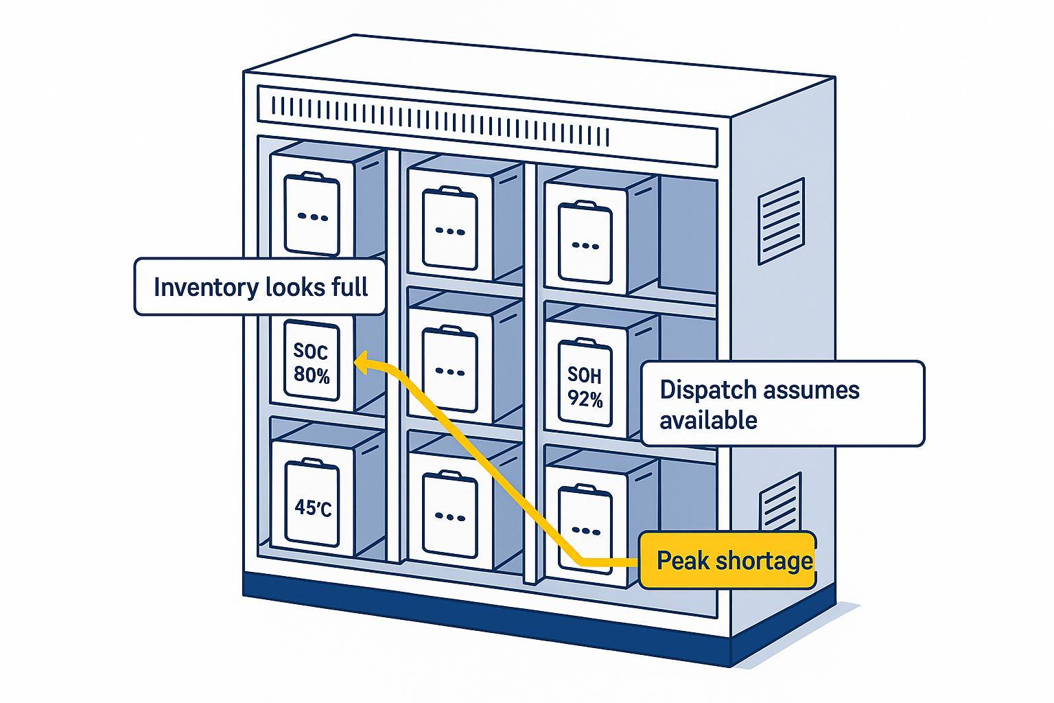
5. BMS and evidence logging
For industrial heavy-lift use, a battery without evidence is a liability.
Regardless of architecture, insist on:
per-cell voltage and temperature visibility (at least at the series-group level)
readable fault flags and a consistent fault dictionary
log export that your team can archive per lot
If your system depends on battery-to-flight-controller coordination, review the integration mindset in UAV Battery Communication Protocol: BMS Data + Flight Controller Integration.
For broader selection framing across payload bands, see Herewin’s heavy-lift overview: 2026 Heavy‑Lift Industrial Drone Battery Selection: 10–200 kg Payload & Endurance Solutions.
Evidence package checklist for architecture selection
Ask suppliers (or internal teams) for an evidence package that can survive a technical review:
Architecture diagram showing power path, isolation elements, and backfeed prevention.
Dynamic discharge test method tied to your worst-case segment (not only static curves).
Voltage sag logs with conditions: SOC band, temperature band, payload/load profile, and recovery behavior.
Thermal mapping that includes connectors/busbars—not just cell surface temperature.
BMS fault dictionary and rules for trip/latch/reclose behavior.
Log export format (fields, sampling rates, timestamps, retention) and an example log.
Lot traceability: incoming inspection rules, binning/matching policy (if parallel), and change control.
Compliance documentation relevant to transport and safety (e.g., UN38.3 evidence where applicable).
How to make the call and what to request
If you’re deciding between architectures this quarter, start with the quick matrix and decision mapping. Then validate your short list using the same worst-case segment test across multiple packs from the same lot.
Two easy-to-miss details that often decide outcomes:
Load-sharing synchronization in parallel packs: don’t assume parallel equals balanced. Use tight cell/branch matching, verify current distribution in logs, and ensure your balancing and protection strategy doesn’t mask an overworked branch.
Mechanical constraint fit: large pouches demand robust support and protection against swelling and abrasion; parallel small-cell builds demand vibration-proof joints and strain relief so contact resistance doesn’t drift in flight.
In heavy-lift fleets, the pack that wins is usually the one with the most predictable voltage sag + hot-spot behavior under step load—paired with BMS data you can export, archive, and audit.
As a practical next step, use the evidence package below as a checklist and score each shortlisted supplier against your mechanical integration constraints, telemetry requirements, and qualification plan. The goal is to compare suppliers on data, not claims.
If you want a second set of eyes on your worst-case segment definition, logs, or evidence package, Herewin typically supports technical reviews aligned to your airframe and duty cycle.
คำถามที่พบบ่อย
Is a 67Ah pouch cell always better for heavy-lift UAVs?
No. Fewer cells can reduce pack overhead and simplify the power path, but large elements increase consequence per failure and place more burden on mechanical support, thermal interfaces, and QA.
Are parallel small-cell packs automatically more reliable?
Not automatically. They can degrade gracefully under some failure models, but real reliability depends on current sharing stability, fault isolation, and backfeed prevention.
What should procurement request beyond a datasheet?
A repeatable dynamic test method, raw logs (voltage/current/temp), a BMS fault dictionary, and traceability artifacts. If you can’t audit it, you can’t operate it.