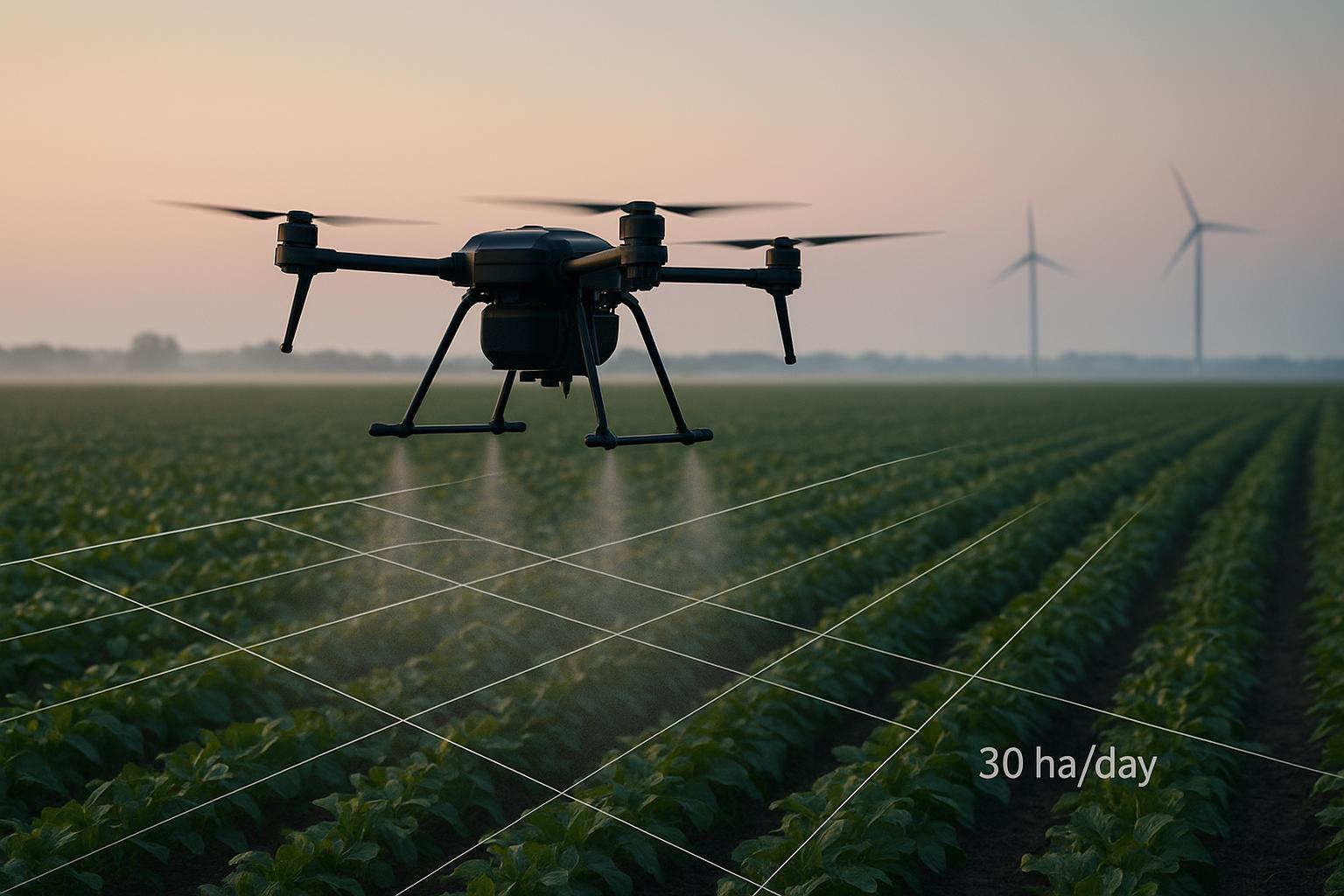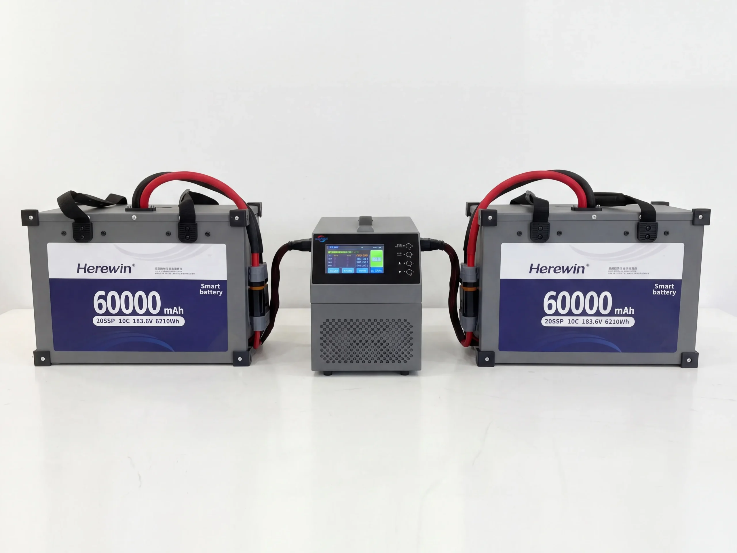


In 2026, drones are living through an energy boom. Long-range logistics airframes are steadily moving toward chemistries that favor energy density and cycle life.
Commercial FPV is the outlier. In film, industrial inspection, and other high-maneuver missions, soft-pack LiPo is still a common default—not because the segment is “behind,” but because FPV’s success criteria are different.
FPV power systems are constrained by two constraints that matter most:
Determinism under burst load (think 120C-class events): the system must deliver predictable thrust right when you ask for it.
Fleet economics under attrition: when airframes and packs are exposed to higher loss rates, “long-life” premiums can turn into stranded cost.
This article breaks the choice down into physics and finance, then turns it into a supplier evaluation checklist you can actually use.
Power vs energy density in FPV LiPo batteries
If you design for energy density, you typically accept constraints that hurt power density. That trade-off isn’t marketing—it comes from transport limits inside the cell.
One practical way to think about it:
Energy density is “how long you can run.”
Power density is “how hard you can punch.”
FPV is punch-first.
In practice, that means you’re often trading a little runtime for cleaner voltage under bursts—and that’s where many “high-energy” designs start to show their limits.
When electrodes get thicker or more heavily loaded, ions and electrons have a harder time moving through the structure fast enough. The result is usually poorer rate capability and more heat at high current (see “Thick electrode design… from an ion-electron transport perspective” (EnergyZ, 2026)). More broadly, academic reviews describe this as a persistent energy–power tension in Li-ion systems (e.g., “Trade-off between energy density and fast-charge capability…” (Chemistry Europe, 2022)).
What this means for an FPV OEM team: if you’re optimizing for burst maneuvering, any chemistry or construction that increases internal transport constraints will usually show up as less voltage stability when you need it most.
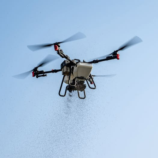
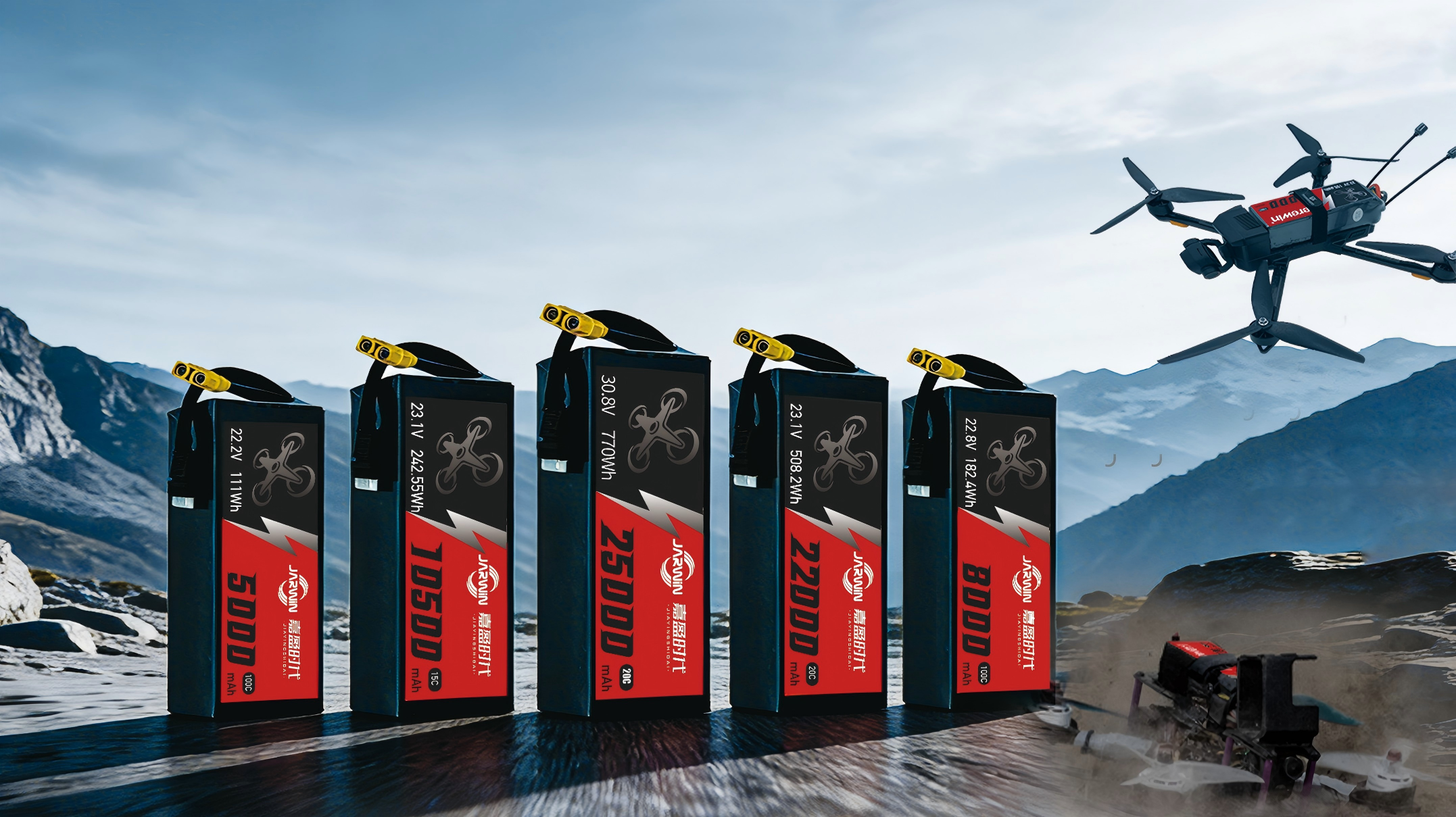
Burst current and C rating in commercial FPV
Endurance UAVs behave like distance runners: long, relatively stable current draw, with slow transients.
For procurement teams, the practical question isn’t the label—it’s whether a pack can hold voltage during repeated burst-current events without excessive sag or heat.
Commercial FPV behaves like a series of explosive sprints:
snap accelerations
prop loading changes during dives/power loops
hard recoveries (instant throttle to arrest a descent)
evasive maneuvers where “thrust now” is the only metric that matters
In this world, average current is a misleading comfort metric. You size for the worst event, not the mean.
Burst current sanity check for FPV packs
You don’t need perfect numbers to understand the scaling. You need the relationship:
C-rate is just current normalized by capacity.
A “120C-class” burst means a current of roughly 120 × capacity (in Ah)—for example, a 1.5Ah pack implies ~180A peak. In procurement terms, define it as a burst window (peak amps + seconds) so suppliers can provide comparable voltage-sag and thermal-rise data.
One important caveat: C-ratings aren’t standardized across brands. Pulse duration, state of charge, temperature, cutoff voltage, and the test fixture (leads/connectors) can all change what a label like “120C” looks like in real voltage stability.
In event-driven FPV, a pack that “looks fine” on average can still fail the mission if it can’t hold voltage through the top 1–3% of load events.
This is why LiPo remains dominant: the segment pays for burst determinism, not just watt-hours.
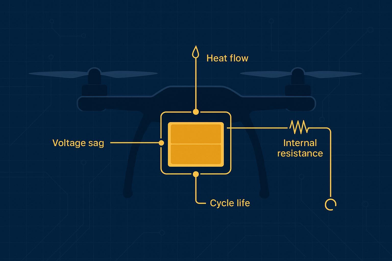
Internal resistance, DCIR, and voltage sag in FPV LiPo packs
At high current, the fight is against internal resistance (IR).
In vendor comparisons, DCIR (and the resulting voltage sag at your target burst current) is often a more reliable signal than headline C ratings.
The core physics is simple and brutal:
Voltage drop under load: V_drop = I × R
Loaded voltage: V_loaded = OCV − (I × R)
So the moment you pull 100+ amps, small resistance differences stop being small.
A clear primer on how internal resistance drives sag (and how you can measure it with practical setups) is SparkFun’s internal resistance tutorial.
Why high-energy designs can fail burst current tests
High-energy-density designs often involve compromises that increase transport limitation risk. Under burst load, those limitations can express as:
Voltage sag (the pack can’t maintain voltage stability)
Heat rise (because I²R losses scale fast)
Reduced control determinism (your tune is now “battery-condition dependent”)
And for an FPV operator, voltage stability isn’t comfort—it’s controllability.
If your power system’s voltage sag pushes you into ESC/FC brownout territory during a recovery maneuver, the mission outcome goes from “pilot skill” to “probability.”
Thermal rise under burst load and why it affects control
Burst performance isn’t only electrical. It’s thermal. Even if two packs deliver the same peak current, the one that manages heat better will:
hold voltage longer across the burst window
recover faster between bursts
degrade slower (which protects batch-level predictability)
At the pack level, the logic is still tied to resistive loss: power loss ≈ I²R.
So, from a design standpoint, thermal headroom is thrust headroom.
Fleet economics: attrition, cycle life, and cost per sortie
In high-attrition FPV environments (tight spaces, aggressive missions, higher crash risk), the question isn’t “how many cycles can this cell deliver in a lab.”
The question is: what does a sortie cost when you include the probability of losing the asset?
A simple Unit Sortie Cost (USC) model
Define:
C_pack = pack cost (USD)
N_cycles = usable cycles before retirement (mission-relevant, not brochure)
P_crash = probability of pack loss per sortie due to crash/incident
A simple expected-cost framing:
Expected sorties before loss from attrition ≈ 1 / P_crash
Effective usable sorties ≈ min(N_cycles, 1/P_crash)
So a first-pass USC estimate can be:
USC ≈ C_pack / min(N_cycles, 1/P_crash)
This is intentionally conservative and simple. It forces one key discipline: you cannot monetize 1,000-cycle life if your operating reality makes the asset unlikely to survive that long.
Example assumptions table (replace with your data)
Input | Conservative | Умеренный | Aggressive | Notes |
|---|---|---|---|---|
Example assumption: Pack cost (C_pack) | $120 | $180 | $260 | Replace with your BOM/landed cost |
Example assumption: Usable cycles (N_cycles) | 80 | 150 | 300 | Mission-relevant (power fade + swelling limits) |
Example assumption: Attrition probability (P_crash) | 2% | 5% | 10% | Use fleet history, not optimism |
Effective usable sorties | min(80, 50)=50 | min(150, 20)=20 | min(300, 10)=10 | 1/P_crash = 50 / 20 / 10 |
USC (USD/sortie) | $120/50 = $2.40 | $180/20 = $9.00 | $260/10 = $26.00 | Formula: USC ≈ C_pack / effective sorties |
What this implies: in high-attrition conditions, paying for extreme cycle life can be a misallocation—because your constraint is loss probability, not electrochemical wear-out.
High-voltage FPV power systems and integration requirements
How far does the FPV power stack go in 2026?
FPV LiPo batteries are now routinely specified in higher-voltage stacks (and not only 6S), because raising voltage can reduce current for the same power—helpful for wiring losses, connector stress, and thermal headroom.
FPV power systems have moved beyond “6S and vibes.” Many OEMs now evaluate higher-voltage stacks for efficiency and current reduction.
But higher voltage raises the bar on:
That shift can shrink your margin for error: small differences in cell balance, connector loss, or protection thresholds can have outsized effects during a burst event.
cell matching and batch consistency
pack-level protection logic
integration between pack signals and vehicle controls
Voltage stability is a tuning input
If the discharge curve and sag behavior shift meaningfully across packs or batches, your tuning becomes brittle:
PID behavior varies between packs
throttle mapping becomes inconsistent
thermal margins change from one sortie to the next
This is where Low IR и voltage stability become procurement criteria, not just engineering preferences.
Smart BMS integration is moving from “nice” to “required”
For commercial OEMs, Smart BMS Integration increasingly means:
real-time voltage/temperature visibility
pack health flags that your FC/mission controller can interpret
traceability (lot codes, QC records) for root-cause analysis
For teams that want a supplier who can support this kind of end-to-end energy system integration, we provide ODM/OEM services that cover pack monitoring and protection—outlined in our drone energy-system solutions.
Lithium battery shipping compliance: UN38.3 and IATA basics
If you’re shipping packs internationally or selling into regulated markets, compliance isn’t a footnote. It determines whether your product is even allowed to move.
For B2B shipments, expect to align on the paperwork buyers and forwarders ask for most often, including UN38.3 test reports, SDS or MSDS documentation, and IATA air-shipping requirements.
At minimum, commercial operations should expect:
UN38.3 transport test documentation
supporting documentation like SDS/MSDS (often requested by carriers)
In the U.S., the Department of Transportation’s PHMSA provides practical guidance in its Lithium Battery Guide (PHMSA, 2024). For air shipments, IATA’s Lithium Battery Guidance Document (IATA, 2026) is a widely referenced packaging/labeling baseline.
For market access:
CE и FCC typically become relevant at the device/system level (electronics emissions compliance), but battery systems still need documentation readiness to avoid being the weak link.
UL2272/UL2595 may apply depending on how the battery system is categorized and sold. Treat UL targets as “as applicable” and confirm scope with your compliance team.
Aviation and carrier compliance support in practice often means being able to produce auditable technical files: test methods, traceability, and transport certifications that survive scrutiny.
Supplier evaluation checklist for burst-capable FPV LiPo packs
If you want fewer surprises, don’t ask “is it 120C?” Ask for proof that maps to your mission profile.
Ask for test evidence you can audit
DCIR measurement method (pulse size, duration, SOC, temperature)
discharge curves showing voltage stability across the burst window
thermal rise data during repeated bursts (not just single peak)
Also ask suppliers to provide raw curves or data exports (time-series voltage/current/temperature) under a fixed, shared test protocol (same SOC, temperature, airflow, pulse/rest schedule, and cutoff). This reduces the risk of comparing “C-ratings” that were produced under different conditions.
Ask for consistency, not just a hero sample
batch-to-batch variance metrics (IR distribution, capacity distribution)
traceability approach (lot codes, QC checkpoints)
Ask for integration readiness
what Smart BMS data is available (voltage, temperature, SOC, protection flags)
what your FC/mission controller can consume (interfaces/protocols)
Ask for compliance readiness
UN38.3 reports and supporting documentation
market-specific documentation plan (CE/FCC at system level; UL where applicable)
Next steps: validate with a burst test
There isn’t a single battery chemistry that wins every mission profile. The practical goal is fit: the pack that delivers the required burst performance, thermal stability, and expected cost per sortie under your operating conditions.
If your missions still reward:
hard recoveries
tight maneuvering
deterministic thrust under burst load
…then LiPo often remains a rational default in 2026.
If you want a faster path to a shortlist, treat evaluation as a controlled experiment:
Define your burst windows (duration, current, rest period)
Fix test conditions (SOC, temperature, airflow)
Compare voltage stability and thermal rise across candidates
Translate results into USC (unit sortie cost) for your real attrition rate