


In 2026, heavy-lift UAV competition won’t be decided by airborne performance alone. It will be decided by ground-side energy certainty: how predictably you can turn packs, prevent incidents, and keep your sortie schedule intact.
As 32S architectures become mainstream, charging infrastructure stops being an accessory and becomes a fleet asset: a risk-control layer and a throughput driver.
For procurement and finance teams, the decision comes down to whether that ground-side certainty can be standardized, audited, and defended as ROI—especially during an 18S → 32S transition.
The practical question is what an operator can standardize on the ground so high-voltage packs move through a repeatable, auditable workflow—especially with mixed fleets and rotating crews.
One workable pattern is to treat charging and the 32S powertrain as a single system—battery, BMS, charger handshake/protocol behavior, compliance documentation, and ODM/OEM validation—rather than a collection of parts.
32S High-Voltage Charging Risks (and the Controls That Matter)
Why Manual Setup Fails Above 100V
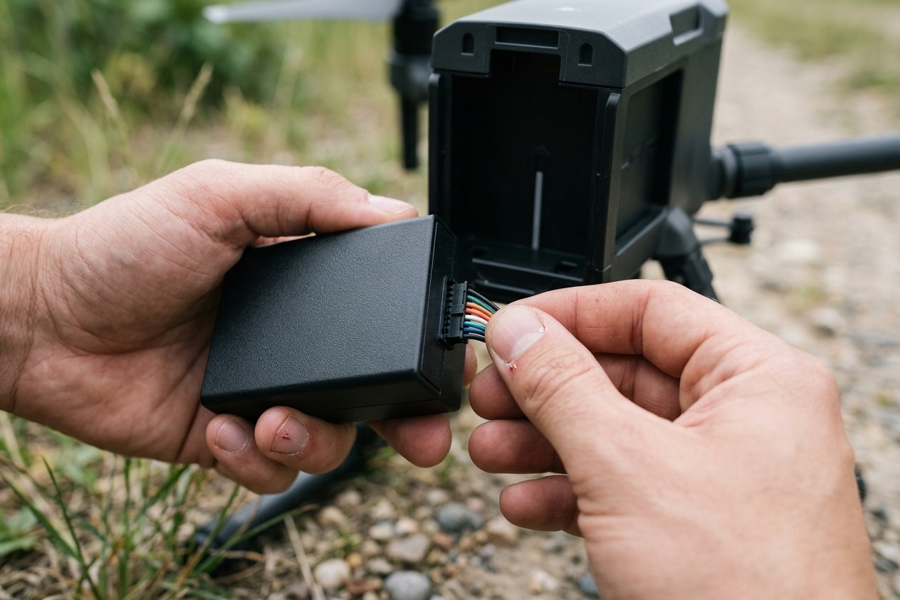
A 32S lithium pack is not “just a bigger battery.” It’s a different risk class.
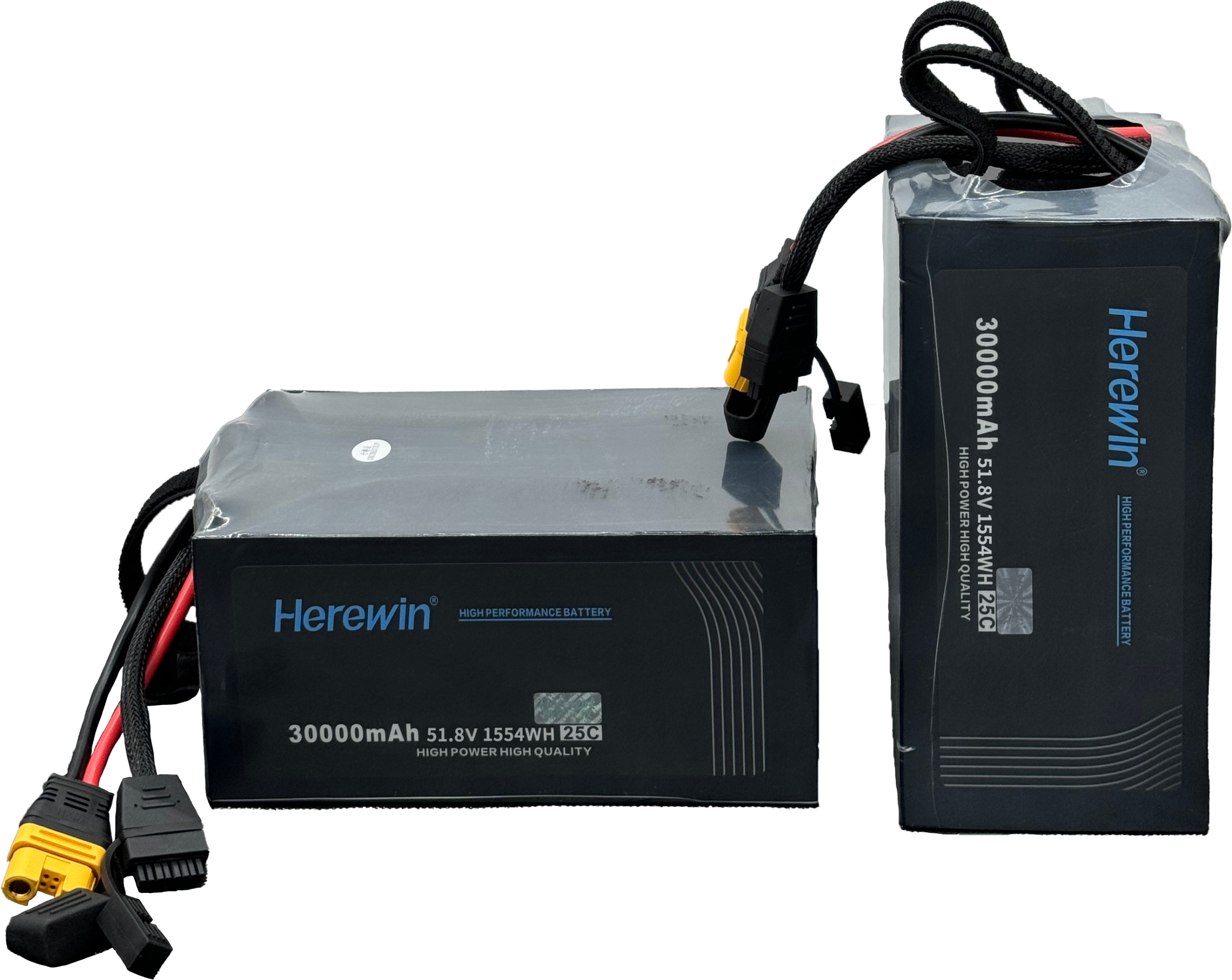
Using the standard Li-ion/LiPo rule-of-thumb—nominal voltage ≈ S × 3.7V and full-charge voltage ≈ S × 4.2V—a 32S pack is roughly 118.4V nominal and 134.4V max (see Battery University’s BU-303 on Li-ion nominal voltage).
At this voltage and energy level, small configuration mistakes stop being “maintenance issues.” They start becoming liability events. In practice, “manual setup” in the field usually means:
Wrong series setting in a mixed fleet (18S/24S/32S)
Incorrect current limit or over-aggressive charge rate
Incorrect charge termination logic during 32S high-voltage charging
Those errors can push cells into electrical abuse conditions—overvoltage, overcurrent, or heat stress—that raise the probability of failure.
Thermal runaway is not a single-point failure; it can become a propagation problem. Once one cell enters runaway, heat and vented gases can trigger adjacent cells, escalating into a pack-level event. See Arthur J. Gallagher’s review of battery risks, thermal runaway, and common triggers like overcharge.
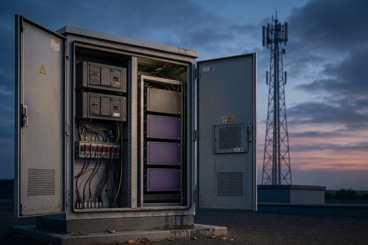
In remote operations, this risk is not limited to the pack itself. A high-energy incident can threaten your mobile charging center—and potentially the transport vehicle supporting it—turning a battery loss into a site shutdown.
Before you put “smart charging” into an SOP, define the minimum control layer you actually need at >100V. For most 32S environments, that means: automatic pack identification, profile locking (so limits can’t be dialed wrong under pressure), temperature-aware throttling with alarms, and basic traceability for post-shift review.
If your charging stack can’t reliably do those four things, it’s not a workflow you can standardize across mixed fleets and rotating crews.
Always follow the pack and charger manufacturer instructions, local electrical and transport regulations, and your documented SOP. This article provides an operations and procurement decision framework—it doesn’t replace a site-specific risk assessment or qualified engineering review.
Herewin’s “Active Safety Shield”: Smart Identification Matching as an Active Control
In procurement terms, “smart identification matching” is best evaluated as a control layer, not a convenience feature.
Our Active Safety Shield is one implementation of that idea: it shifts setup from “human memory under pressure” toward a protocol-driven interaction between pack and charger.
That matters because for high-voltage charging, your risk isn’t only chemistry. It’s variance:
variance in technician training
variance in shift handoffs
variance in pack mix
variance in field conditions
Intelligent protocol behavior doesn’t eliminate physics. But it can eliminate preventable misconfiguration pathways.
Eradicating Human Error: The Financial Impact of “Zero-Touch” Operations
Think of manual configuration as a hidden line item: a Human Variance Tax.
It shows up as:
avoidable pack stress (accelerated degradation due to incorrect limits)
near-miss incidents (extra checks, lost time, decision delays)
increased supervision requirements (skilled staff babysitting chargers)
audit friction (harder to prove consistent procedures)
In high-voltage environments, zero-touch charging operations aren’t about making teams lazy. They’re about removing the biggest uncontrolled variable from an industrial process: the operator.
When you can standardize charging to a connect-and-confirm workflow, you can scale crews without scaling incident probability at the same rate.
A Practical Solution Pattern: Standardized Charging + 32S Power Systems
Most charging discussions focus on power (kW) and speed (minutes). In 32S operations, the bigger lever is standardization: a workflow that is consistent across sites, shifts, and pack variants.
A system-level delivery approach typically includes five layers:
Battery pack engineering for the aircraft’s load profile and duty cycle
BMS logic and telemetry that enforces electrical and thermal limits
Identification and handshake behavior so the charger can select the right profile automatically
Safety and compliance documentation that makes SOPs auditable across teams and regions
ODM/OEM execution so the pack, harnessing, and charging workflow are validated together (not assembled ad hoc)
Our UAV power stack follows that bundling logic. The charger is treated as part of the battery system, and the battery system is treated as part of operations. The value isn’t “more features.” It’s fewer ways for a crew to apply the wrong settings under time pressure.
In other words, once your ground workflow is standardized, higher power (like 10.4kW) becomes a predictable throughput gain—not a new source of process risk.
Fleet Utilization ROI: What Faster Charging Changes
The “Ground-Idle” Tax: A Simple ROI Framework
Heavy-lift fleets rarely lose money because they can’t fly. They lose money because they can’t fly when they need to—because packs are queued, monitored, or held for safety checks.
To get a decision approved, quantify that loss in a way a finance team can validate and an ops team can measure.
Annual Operational Recovery (AOR) = (Labor Optimization) + (Avoided Asset Damage) + (Additional Sortie Revenue)
To keep AOR defensible, treat every number below as a scenario input, not a universal claim. Replace the example assumptions with your site’s measured turnaround times, staffing model, and mission margin—and document where each figure comes from (logs, SOP timing studies, or dispatch records).
To keep this auditable, start with an inputs table and label assumptions.
Model input | Symbol | Example assumption (edit for your site) | Notes |
|---|---|---|---|
Fleet size (aircraft) | F | 10 | total active aircraft |
Charge time—traditional (minutes) | T₁ | 45 | time to ready-to-fly |
Charge time—smart high-power (minutes) | T₂ | 15 | time to ready-to-fly |
Sorties per aircraft per day (baseline) | S₀ | 5 | your current throughput |
Sortie gross margin ($) | GM | 120 | revenue minus variable mission costs |
Ground staff fully loaded rate ($/hr) | LR | 28 | wage + overhead |
Monitoring labor per charge (minutes) | M | 45 vs. exception-based checks | traditional vs. controlled workflow |
Operating days per year | D | 260 | adjust for seasonality |
For time-to-charge intuition, most industries start with a simple approximation: time ≈ kWh ÷ kW, then adjust for tapering and acceptance limits. See Recharged’s charging-time explainer и Power-Sonic’s discussion of acceptance-rate limits.
Now translate time back into utilization. If a 45-minute turnaround becomes 15 minutes, you’re not only saving 30 minutes. You’re reclaiming schedule flexibility—the ability to fit more cycles into the same operational window.
Your scenario (example inputs):
Conventional workflow: 45 minutes charging + 1 ground staff actively monitoring
Controlled workflow (example implementation with identification matching and profile locking): 15 minutes charging + reduced continuous manual monitoring
“Reduced continuous manual monitoring” is not “unattended charging.” It assumes identification matching and profile locking are enabled, temperature limits and alarms are active, and trained personnel remain on-site to respond to exceptions per SOP.
Under those assumptions, the resulting throughput gain can be directionally meaningful (illustrative scenario only):
Example: ~3.3 additional sorties per aircraft per day only if charging is the binding constraint and mission duration, crew availability, battery cooling/handling time, and airframe maintenance windows are not the bottleneck
For a 10-aircraft fleet: ~33 incremental sortie slots/day (illustrative)
What matters is not the exact 3.3. What matters is that fleet utilization converts ground time into revenue capacity—and that you can validate the inputs with your own dispatch records and charging logs.
What High-Power Charging Changes Operationally
From a procurement lens, high-power charging shouldn’t be treated as a standalone spec. It’s a throughput variable that affects queueing, staffing, and schedule predictability.
It changes three things at once:
Queue length (fewer packs waiting)
Supervisor dependence (less expert babysitting)
Schedule predictability (less “maybe-ready” uncertainty)
In a standardized, controlled workflow, a higher-power configuration (for example, 10.4kW in our setup) becomes a predictable throughput gain—not a new source of process risk.
Treat charging like an SLA-controlled subsystem. If you can’t explain your “ready-to-fly time” distribution (p50/p90) and your safety controls, you don’t have charging infrastructure—you have a bottleneck.
One way to make this auditable is to map your controls to measurable signals: pack ID matching and profile locking reduce overrides; temperature throttling and alarms show up as temperature-event logs; traceability turns shift performance into a reviewable record (p50/p90 ready-to-fly time, exception rate, and stop/restart counts).
CAPEX Planning for the 18S → 32S Transition
Avoiding Charger Obsolescence During the Shift
The 2026 reality is messy: mixed fleets, mixed pack standards, mixed charging workflows. The risk isn’t that a charger “stops working”—it’s that it stops fitting your evolving fleet standard before you’ve recovered the investment.
If you purchase chargers that only support lower-voltage packs, a common outcome during an 18S → 32S transition is economic obsolescence:
the asset is still usable
but the fleet standard moves past its voltage range
and it becomes a throughput constraint (or a tool reserved for edge cases)
Instead of treating charger CAPEX as a single-point “speed purchase,” treat it as a readiness asset and evaluate it over your expected transition window (often several years, depending on fleet refresh cadence and deployment model).
From an operations lens, wide-voltage support matters because it can reduce complexity during the shift. Fewer charger SKUs, fewer profile-selection decisions, and fewer “special-case” exceptions in SOPs typically translate into lower training overhead—and fewer opportunities for misconfiguration when crews are rotating or deployments are remote.
A practical procurement/finance checklist to keep this decision defensible:
Voltage coverage across current and planned pack standards (e.g., 18S–32S)
Compatibility risk (protocol/handshake behavior, connector/harness constraints)
Operational complexity (SKU count, profile selection steps, exception handling)
Compliance and auditability (documentation, traceability, verification package availability)
Residual value and redeployability (can the charger be reassigned across sites or platforms?)
For teams already standardizing energy infrastructure, this approach also pairs naturally with Herewin’s broader UAV power ecosystem—see Herewin’s drone solutions overview.
The Mobile Power Hub: Enabling Global Rapid-Deployment Strategies
Pickup-Bed Integration: Modular Infrastructure for Remote Hubs
Field SOP Snapshot (Template)
Use this checklist to standardize a mobile charging hub workflow. Adapt it to your site risk assessment and local regulations.
Pre-shift setup (baseline checks)
Verify charger model/firmware and approved voltage range (e.g., 18S–32S) per SOP
Verify grounding/earthing method for the vehicle or containerized hub (per local electrical code)
Inspect connectors, harnessing, and strain relief; tag/replace any worn parts
Verify fire response equipment and exclusion zone markings are in place
Connect-and-confirm workflow (per charge, human-in-the-loop)
Connect pack → verify automatic identification and correct profile selection → verify current limit and termination logic are locked
Start charge → verify temperature sensing is active and alarms are audible/visible
Record key log fields (recommended): pack ID, start/end time, start SoC/voltage, peak temperature, and any exceptions
Common exceptions (what to do)
Profile mismatch / ID fail: stop charge, isolate pack, switch to manual review process, and log the event
Over-temp warning: stop or throttle per SOP; do not resume until root cause is identified (ambient heat, airflow, pack damage)
Repeated imbalance / early termination: quarantine pack for inspection and balancing review
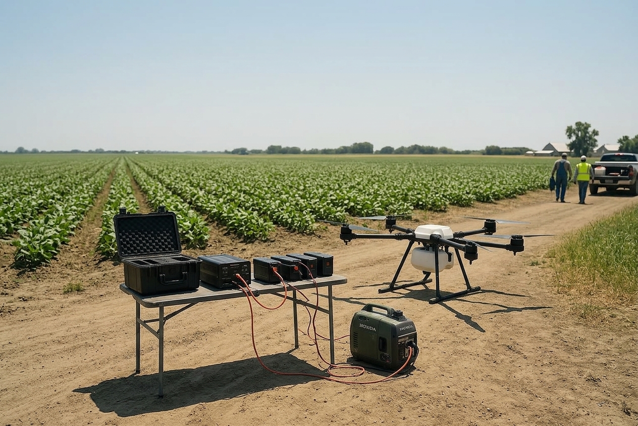
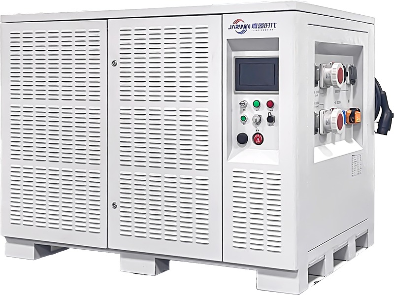
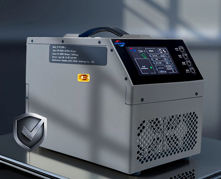
Fixed charging infrastructure is capital intensive and slow. For heavy-lift operations that move—agriculture, logistics corridors, border work, remote inspection—the winning model is often a lean, standardized kit you can redeploy with the same SOP.
A compact, high-power hardware stack allows a normal 4×4 pickup to become a mobile power hub—a deployable energy node.
Why Lean Infrastructure Wins in Weak-Grid Regions
In weak-grid environments, the constraint isn’t ambition. It’s power quality, uptime, and logistics.
This is where a mobile hub strategy changes market entry math:
reduces the fixed-asset threshold for new regions
shortens time-to-operate (deploy a kit, not build a site)
supports 24-hour rapid deployment plans
To keep this audit-friendly, treat it as a deployment checklist:
define the minimum power and safety envelope
standardize your pack/charger pairing rules
enforce a documented handling procedure
For high-voltage battery handling, industrial safety guidance consistently prioritizes training, restricted access, and documented procedures. A practical overview is provided in the Canadian Centre for Occupational Health and Safety guidance on high-voltage batteries in electric/hybrid machinery.
And if your operation involves transport and operator governance, aviation-adjacent frameworks emphasize formal risk assessment and standardized procedures—see IATA’s Lithium Battery Risk Assessment Guidance for Operators.
High-Power Charging as a Strategic Business Asset
In 2026, heavy-lift advantage will go to the teams that can run at lower risk and higher turnaround rate—consistently, across sites, shifts, and mixed fleets.
Smart high-power charging earns budget because it does two things at once:
It reduces the probability and blast radius of high-voltage errors.
It converts ground idle time into utilization—and utilization into revenue capacity.
If you want to benchmark your current ground workflow against a standardized 18S–32S-ready charging approach (battery + BMS + charger handshake + documentation), you can start with Herewin’s heavy-lift drone battery solutions guide—or contact our team to discuss an 18S–32S charging workflow for your fleet.
Compliance & Verification Notes
Because high-voltage charging is safety-sensitive, procurement teams often need evidence—not just features. Based on your project scope, destination market, and internal EHS requirements, we can support a verification package that may include:
Applicable compliance documents and certifications (e.g., CE / UL / UN38.3 / ISO, as applicable to the specific model and market)
Test reports and/or agreed acceptance criteria (thermal limits, protection behavior, charge profile definitions), including the measurement method used
Traceability items for audits (model/firmware identification, packing list, and serial/batch references as applicable)
Request the package during the RFQ stage so it can be aligned to your target market requirements, documentation format, and review workflow.
ЧАСТО ЗАДАВАЕМЫЕ ВОПРОСЫ
Does fast charging automatically destroy cycle life?
Not automatically. Cycle life impact depends on how charging is controlled (voltage limits, current limits, temperature window, balancing) and how consistently the process is followed. The decision point is whether your workflow reduces abuse conditions—especially in mixed-fleet field operations.
What’s the single biggest risk in 32S charging operations?
Configuration error compounded by high voltage: a wrong setting can push cells into overvoltage/overcurrent stress, increasing the probability of thermal events. That’s why protocol intelligence and standardized SOPs matter.
How do you justify charging CAPEX during an 18S → 32S transition?
Treat it as obsolescence insurance. Wide-voltage (18S–32S) support reduces stranded tools, reduces training SKUs, and keeps your ground ops standardized while the fleet standard evolves.