










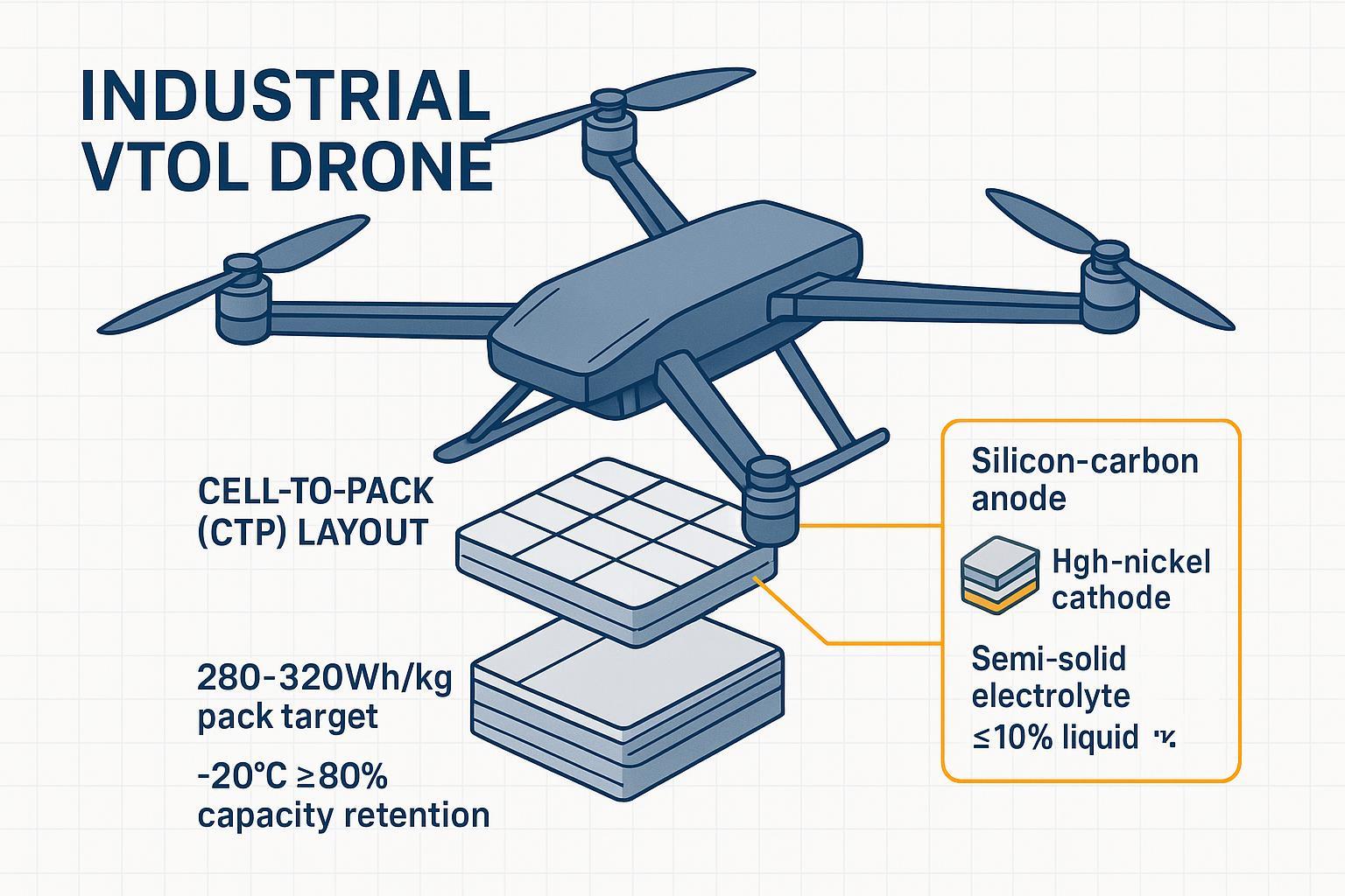
Achieving pack-level targets of 280–320 Wh/kg (with cell-level >350 Wh/kg) is no longer theoretical—it is the practical benchmark for 2026. However, hitting this band requires a fundamental shift: teams must treat energy density as a system-level architecture problem, not just a single-component upgrade.
The most practical “High-Density Stack” for R&D teams today synchronizes three layers:
- Chemistry: Semi-solid electrolytes (≤10% liquid) paired with Silicon-Carbon anodes (~5–10 wt% Si).
- Structure: Cell-to-Pack (CTP) pouch architecture to eliminate redundant module weight.
- Intelligence: Active cell balancing and mission-aware charge windows (80–90% SoC).
Independent characterization has already validated semi-solid pouch cells near 347.5 Wh/kg and UAV packs in the 303–313 Wh/kg range. The technology is ready; the next step is rigorous validation against lab abuse tests and UN38.3/MSDS compliance.
Core Principles: Treating Energy Density as a System Target
To convert theoretical chemistry into mission endurance, we evaluate energy density through three interdependent lenses:
The Dual-Density Requirement
- Gravimetric Density (Wh/kg): The primary driver for hover efficiency and payload capacity.
- Volumetric Density (Wh/L): Critical for integration into slim fuselages or carbon-fiber booms where space is at a premium.
The High-Load Trade-off Triangle
- The classic tension between Safety, Energy, and Cycle Life becomes acute under UAV-specific load profiles (e.g., high-current VTOL transitions). Pushing cut-off voltages to 4.45V requires more than just better materials; it requires structural and thermal safeguards.
The Coherent Stack (2026 Roadmap)
We move away from one-off “silver bullet” upgrades in favor of a synchronized architecture.
- Chemistry: Semi-solid electrolytes (to reduce volatile solvents) + 5–10 wt% Silicon-Carbon anodes.
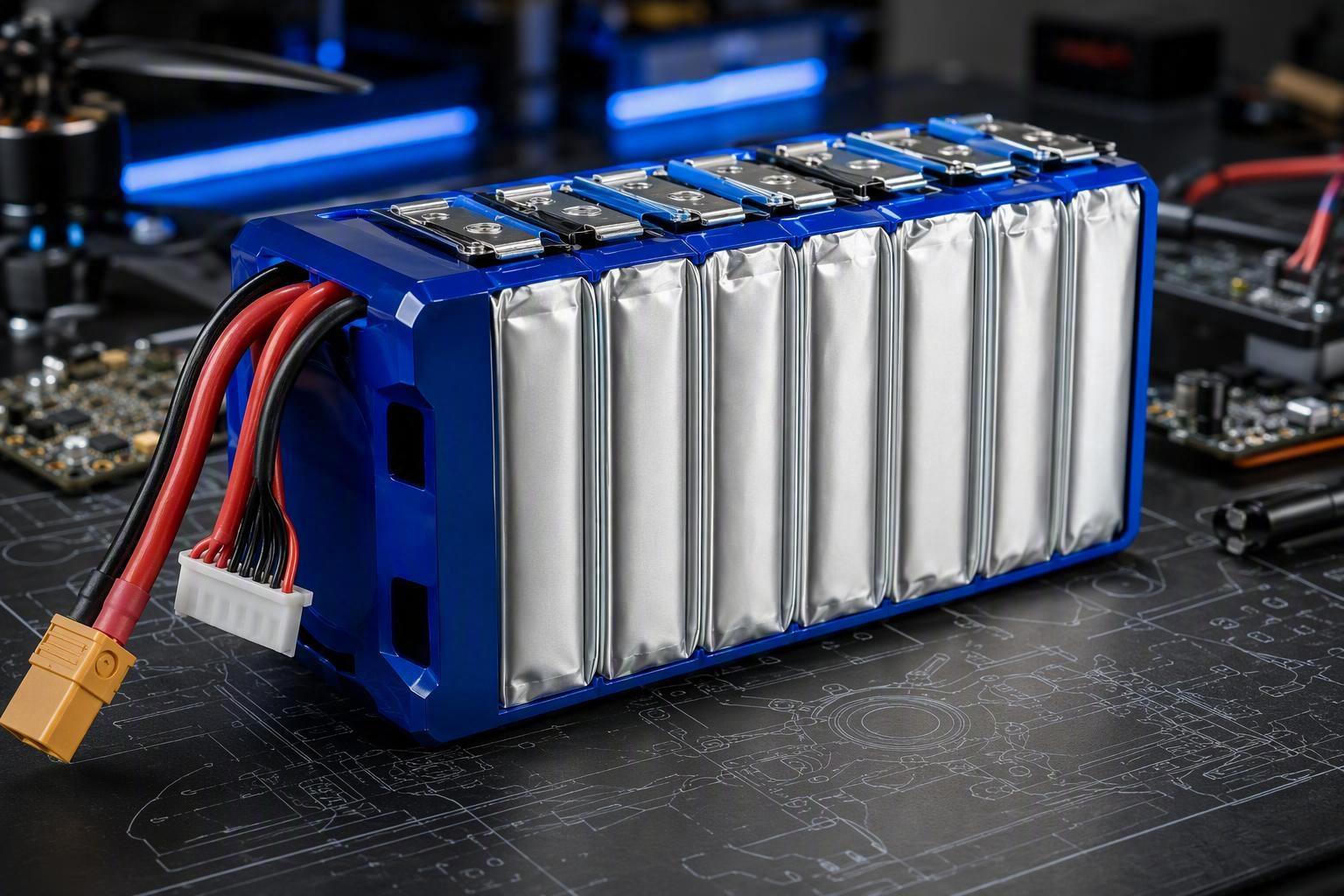
- Structure: Cell-to-Pack (CTP) with pouch cells to eliminate redundant module housings.
- Intelligence: Active BMS balancing and mission-aware windows (80-90% SoC) to preserve the electrode interface over 1,000+ cycles.
Materials that unlock higher specific energy
Silicon–carbon anodes at 5–10 wt% Si
Graphite theoretically caps at 372 mAh/g; integrating modest silicon fractions is essential to reach the >350 Wh/kg cell frontier. To ensure stability, adopt a “Stress‑Buffered” composite design:
- Mechanical reinforcement: utilize conductive networks (for example, CNT‑enhanced binders) to preserve electrical connectivity and mitigate pulverization during ~300% local silicon expansion.
- Interfacial engineering: favor FEC‑rich additive packages that promote formation of LiF‑rich SEI layers with higher mechanical integrity at elevated cut‑off voltages.
- Strain distribution: incorporate surface‑coated Si or Si@C clusters to distribute mechanical strain and prevent SEI fracture over extended cycling.
Technical Basis: These practices reflect recent peer‑reviewed reviews and research on Si‑anode expansion mechanisms and mitigation strategies, as detailed in “Surface and Bulk Stabilization of Silicon Anodes” (ACS Applied Materials & Interfaces, 2024) and the open‑access review Nguyen et al., 2024 (PMC review on semi‑solid and interface engineering).
High‑Ni cathodes at higher voltage (4.35–4.45 V)
Pursue Ni-rich NCM/NCA chemistries with practical specific capacities of 200–220 mAh/g. At the 4.4–4.45 V frontier, interfacial gas generation and oxygen release risks increase; our mitigation pathways include particle surface coatings, dopants, and targeted electrolyte additive packages. However, 4.45 V should be treated as a capability to be validated by rigorous abuse testing and national-lab modeling rather than a default operating point.
Semi‑solid electrolyte (≤10% liquid): definition and advantages
We define semi-solid precisely as a solid-dominant electrolyte network (polymer/ceramic composite) with a minor liquid phase (≤10% by weight), engineered for 0.1–1 mS/cm conductivity while significantly lowering free solvent. Well-dispersed ceramic fillers (Al2O3 / TiO2 / SiO2) in polymer matrices raise mechanical strength, suppress dendrite penetration, and improve high-temperature robustness. Recent reviews document improved low-temperature retention (≥80% at −20°C) and enhanced abuse tolerance for these quasi-solid formulations.
From cell to pack: CTP pouch architecture and the math that gets you to 280–320 Wh/kg
Pouch cells reduce can mass and allow denser stacking; Cell‑to‑Pack (CTP) removes module housings to cut inactive mass. Use a simple density model to translate cell gains into pack gains:
Pack Wh/kg ≈ (Cell Wh/kg × Packing factor × Active‑mass share) ÷ (1 + Inactive‑mass fraction)
| Metric | Standard Pouch | Optimized CTP Architecture |
|---|---|---|
| Cell specific energy | 350 Wh/kg | 360 Wh/kg |
| Packing factor | 0.90 | 0.94 |
| Active‑mass share | 0.97 | 0.97 |
| Inactive‑mass fraction | 0.15 | 0.12 |
Worked result (optimized):
- Numerator = 360 × 0.94 × 0.97 = 328.05 → Pack Wh/kg ≈ 328.05 ÷ 1.12 ≈ 293 Wh/kg. (Baseline computes to ≈266 Wh/kg.)
Efficiency levers (compressed):
- Separator thinning (≈ −30%) to raise packing factor.
- Module elimination and lightweight frames (≈ −20% inactive mass).
Parameter snapshots:
- Cell specific energy: 345–365 Wh/kg.
- Packing factor (CTP): 0.90 → 0.94.
- Pack inactive mass fraction: 0.15 → 0.12.
- Allowable swelling: ≤ 3% volume over life.
These conservative, manufacturable levers plus modest cell improvements create a clear path from a ~266 Wh/kg baseline to ~293 Wh/kg optimized packs. Validate with full mass breakdowns, DCIR screening, abuse tests, and UN38.3/MSDS before flight qualification.
BMS and Mission Operations: Turning Theoretical Wh into Flight Minutes
Active balancing resolves the “weakest‑cell caps the pack” constraint by transferring charge between cells instead of dissipating it as waste heat. While standard passive systems typically offer currents ≤ 0.3 A per channel, high‑power active modules are designed for 1–3 A transfers with high transfer efficiency.
Active‑Balancing Routine (Operational Logic)
- High‑frequency sampling — sample telemetry at 1 Hz: individual cell voltages, per‑cell and pack temperatures, and pack current.
- Safety interlocks — if any cell temperature > T_max or < T_min, immediately disable active balancing and flag the event for fault handling.
- Advanced state estimation — compute each cell’s SoC using an OCV‑plus‑impedance model (OCV+R) rather than raw voltage alone to reduce estimation error under load.
- Charging‑window behavior — during charge, if SoC variance ≳ 2% (or voltage spread dV ≳ 30 mV), select the highest‑SoC cell as the source and the lowest‑SoC cell as the sink; initiate a transfer current proportional to variance, clamped to 0.5–3 A, while monitoring temperatures and pack current limits.
- Discharge‑window behavior — within a safe mid‑SoC band, allow limited transfers if SoC variance ≳ 3%; limit transfer current to ≤ 1 A and enforce thermal guardrails.
- Convergence priority — as the pack approaches cutoffs, taper transfer currents so all cells converge to EoC/EoD thresholds simultaneously, minimizing early cutoffs.
- Life‑cycle maintenance — log every balancing event (timestamp, source/sink cells, ΔSoC, current, duration) for aging analysis; perform a scheduled full equalization cycle every 3–6 months to recalibrate SoC estimation and detect DCIR drift.
Enforce thermal guardrails for every transfer, and include automated rollback to passive balancing if any imbalance action causes temperature excursions or unexpected DCIR changes.
Mission charge / discharge windows (Best Practices)
- Daily operations: target charge cap = 80–90% SoC; maintain a ≥ 20% SoC landing reserve, especially for cold‑weather missions.
- Periodic calibration: run a full charge + active equalization every 3–6 months to realign SoC models and cell balance.
- Cold‑weather SOP: when ambient < 5 °C, preheat the pack ≥ 15 min to raise core cell temperature to ~5–20 °C before takeoff; reduce allowable C‑rate at −20 °C to limit plating risk.
For step‑by‑step field procedures and SOP templates, see Herewin’s mapping & inspection battery operations guide and cold‑weather preheat techniques: Herewin mapping & inspection guide and Herewin cold‑weather SOP.
Thermal and Mechanical Integrity for Pouch‑CTP Packs
Design compression frames that maintain uniform pressure across the pouch stack to accommodate micro‑swelling without inducing edge delamination. Build clear thermal paths from cell faces to heat spreaders or cold plates using compliant interface materials; avoid sharp thermal gradients near busbars. Ceramic‑coated separators and peer‑reviewed separator‑coating studies support thinner, more stable separators when combined with validated abuse performance.
Safety Note: Semi‑solid packs still contain reactive components—do not open in the field. Exposure of electrolyte to moisture can produce irritating or toxic species.
Validation and Compliance
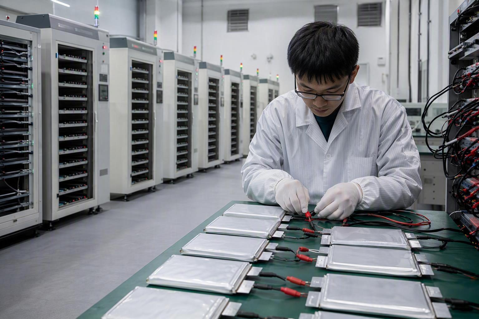
Treat the 280–320 Wh/kg target as a verification program, not just a design ambition. Validation must be grounded in empirical data:
- Abuse tests — Puncture (nail), overcharge, and thermal‑runaway characterization with maximum temperature and heat‑release profiles recorded. Set conservative acceptance thresholds before enabling 4.45 V operation.
- Low‑temperature resilience — Demonstrate ≥80% capacity retention at −20°C at an agreed C‑rate; include thermal soak and pulse tests to characterize power fade under mission loads.
- Cycle protocols — Verify either ≥1,200 cycles at a 1.5C dynamic profile or ≥3,000 cycles under 50% DOD shallow cycling, with DCIR and capacity‑spread statistics reported at regular intervals.
- Transport & documentation — Provide UN38.3 test summaries and MSDS to buyers; ensure shipping SoC policies and packaging meet current IATA (2026) and UL guidance.
Also review national‑lab modeling and aerospace safety guidance to align expectations with evidence and to validate high‑voltage pack thermal behavior.
Micro case examples (what good looks like)
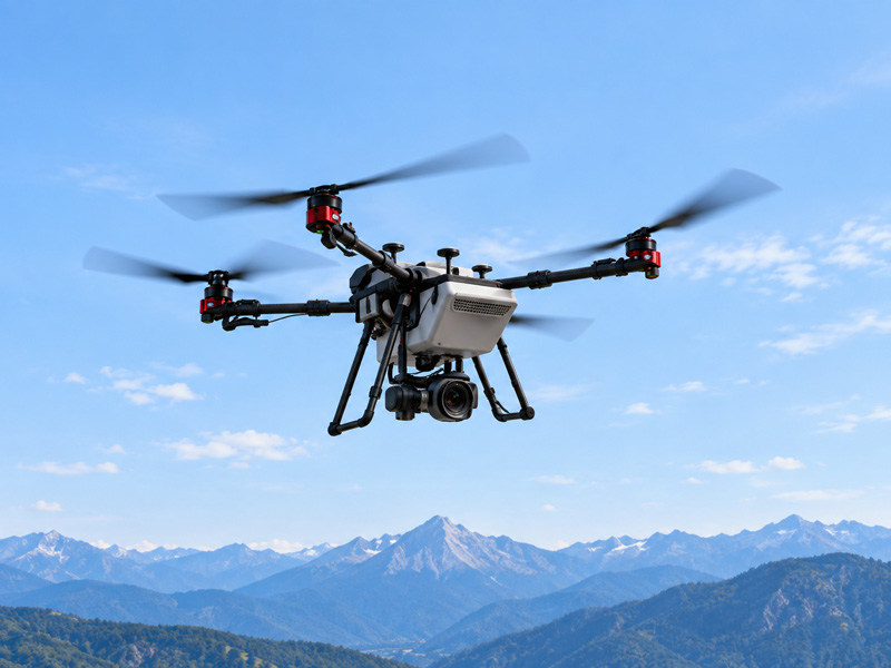
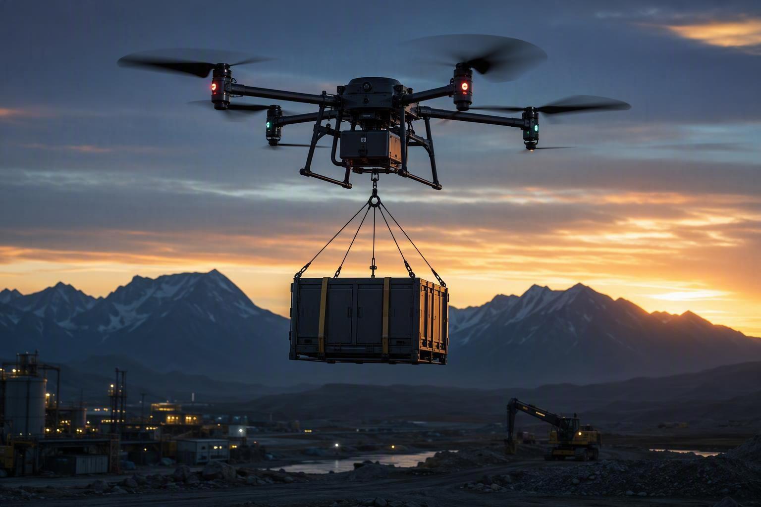
Heavy‑lift VTOL — Pack-level Energy Uplift
- Strategy: Utilize semi‑solid pouch cells (340–360 Wh/kg) in a dedicated Cell‑to‑Pack (CTP) layout.
- Performance: Achieved a packing factor of ≈0.93 and reduced inactive mass to 10–12%, resulting in a modeled pack density of 290–305 Wh/kg.
- Mission Impact: For identical payloads, this configuration yields ≈30–50% longer hover/transition endurance versus standard liquid battery baselines (150–250 Wh/kg).
- Evidence: Herewin internal cell and pack data (≈340 Wh/kg nominal for semi‑solid pouch cells) and industry pack disclosures support the feasibility of this range; treat lab and field numbers as subject to independent verification.
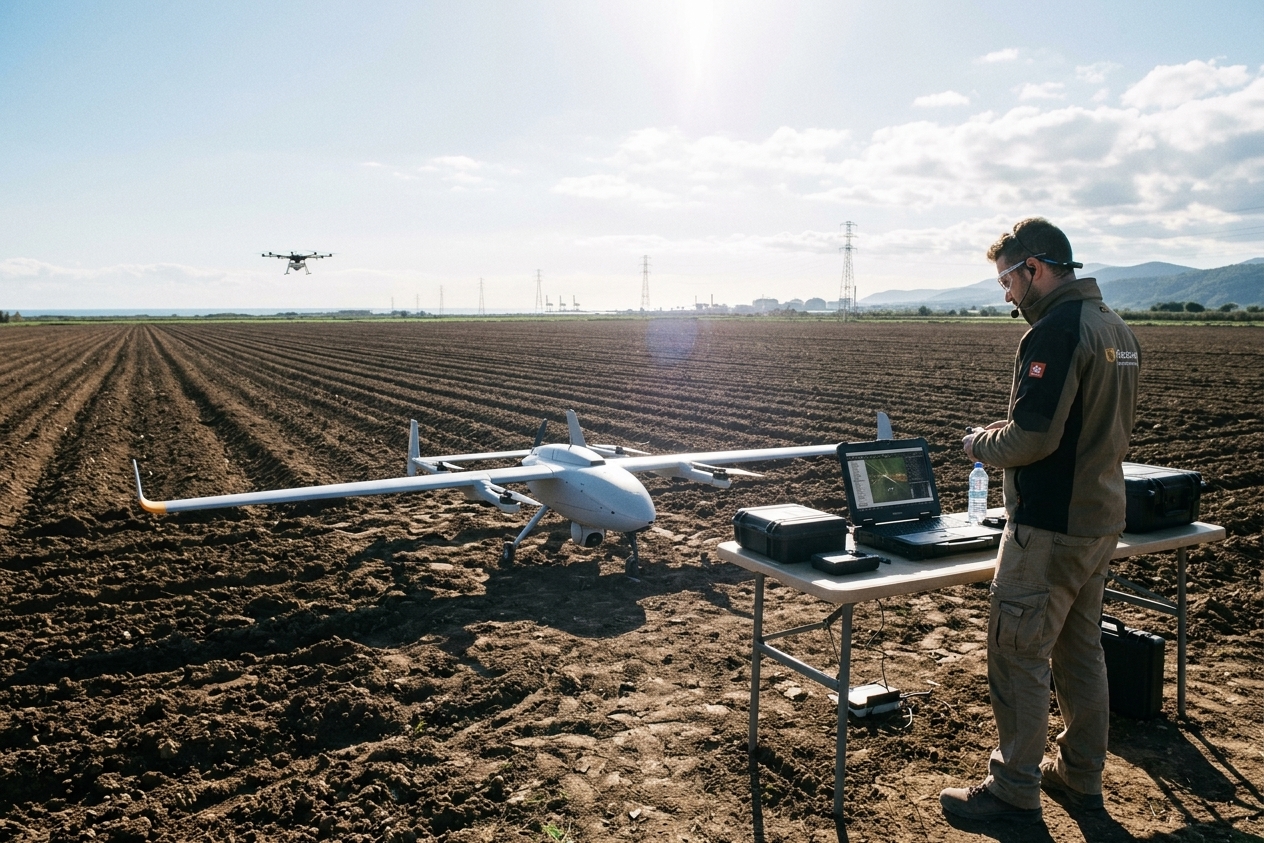
Mapping/Inspection Drone — Cold‑weather Reliability
- Cold Tolerance: Laboratory studies and low‑temperature tests indicate ≥80% capacity retention at −20°C for semi‑solid systems, with reported discharge‑power improvements of ~25% versus conventional liquid formulations.
- SOP Optimization: Pair chemistry selection with pre‑flight preheating (raise cell core to ≈20°C for ≥15 minutes) and an 80–90% SoC charge cap for maximum cycle stability and predictable RTH margins. See Herewin’s mapping & inspection battery operations guide for SOP templates and monitoring tips.
- Operational Outcome: Operators report significantly fewer mid‑mission voltage sags and more reliable Return‑to‑Home (RTH) triggers under extreme cold when these procedures are followed; quantify in your program with A/B fleet tests.
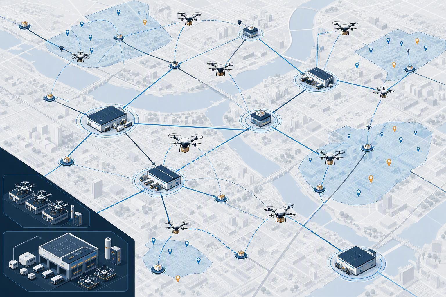
High‑Frequency Logistics Fleet
- Source: Derived from operator and vendor reports in high‑frequency field deployments and Herewin internal validation summaries.
- Test Conditions: Mixed mission profiles featuring dynamic 1.5C discharge windows and routine 5C fast‑charging protocols.
- Performance Outcome: Packs reportedly sustained ≥1,200 cycles while maintaining usable capacity at −20°C under conservative DOD and thermal management policies.
- Verification Action: These are operator‑reported and internal results; independent lab verification (abuse, cycle, and low‑temperature tests) is recommended prior to final design qualification.
Disclosure: Herewin is our company. The VTOL and logistics examples above reference our semi‑solid pouch CTP architecture; detailed datasheets and UN38.3/MSDS documentation can be provided upon request (NDA may be required).
PERGUNTAS FREQUENTES
Is cell‑level ≥350 Wh/kg realistic in 2026?
Independent characterization has reported a semi‑solid pouch cell at ~347.5 Wh/kg; treat 350 Wh/kg as an upper‑bound target pending your own validation and abuse tests.
What’s the safest path to 4.45 V operation?
Use Ni‑rich cathodes with surface coatings/doping, pair with FEC‑rich additive packages, and qualify at lower cutoffs first. Only raise voltage after abuse tests confirm acceptable heat‑release and gas‑evolution behavior.
How much does active balancing add to usable capacity?
Literature consensus explains the mechanism, but robust UAV‑specific percentages are scarce. Expect gains from minimizing early cutoffs due to weak cells, especially after aging; validate with A/B fleet tests.
Does shallow cycling really extend life?
Foundational studies indicate partial‑DOD cycling extends life, sometimes significantly, but UAV‑specific post‑2024 data are limited. Adopt 80–90% charge caps and ≥20% landing reserves, then measure on your mission profiles.
Next steps for R&D teams
To bridge the gap between technical roadmap and field deployment, we recommend the following engineering milestones:
- BOM Configuration: Lock a pilot Bill of Materials around Si-C (5–10 wt%), Ni-rich cathodes at validated cutoffs, semi-solid electrolyte, and a CTP pouch layout.
- Dual-Lane Validation: Execute parallel testing lanes: (1) Safety (abuse, low-temp, voltage limits) and (2) Endurance (target mission profiles). Instrument all packs to monitor SoC variance and DCIR spread.
- Peer Review: For a neutral datasheet audit or to benchmark your validation matrix against industry frontiers, submit your draft test plan for a gap analysis.
Authoritative Sources & Standards
To validate your 2026 roadmap against industry benchmarks, refer to these primary standards:
- Aerospace Safety — refer to the NASA NESC Technical Update (2024) for workshop findings on airborne and spacecraft battery safety practices.
- Silicon Anode Mechanics — for deep dives on expansion mitigation, consult peer‑reviewed studies such as ACS Applied Materials & Interfaces (2024–2025) and recent Nature Energy perspectives on silicon anodes.
- Cell & Pack Modeling — use Argonne National Laboratory BatPaC (2024) for definitive modeling parameters and pack engineering limits.
- Compliance & Transport — ensure your deployment plan aligns with the UN38.3 Test Summary (PHMSA, 2024), the IATA Lithium Battery Guidance (2026), and the UL 1642 cell safety standard.
Ready to bridge the gap from roadmap to flight? Contact Herewin Engineering to schedule a pack integration review.



 Português do Brasil
  English
  Español
  한국어
한국어  Deutsch
  Français
  日本語
日本語  Русский
  Bahasa Indonesia
  ไทย
ไทย  العربية
  Italiano
  Nederlands