







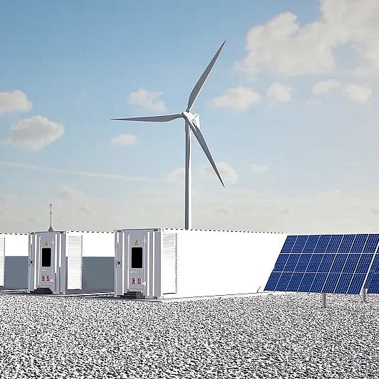




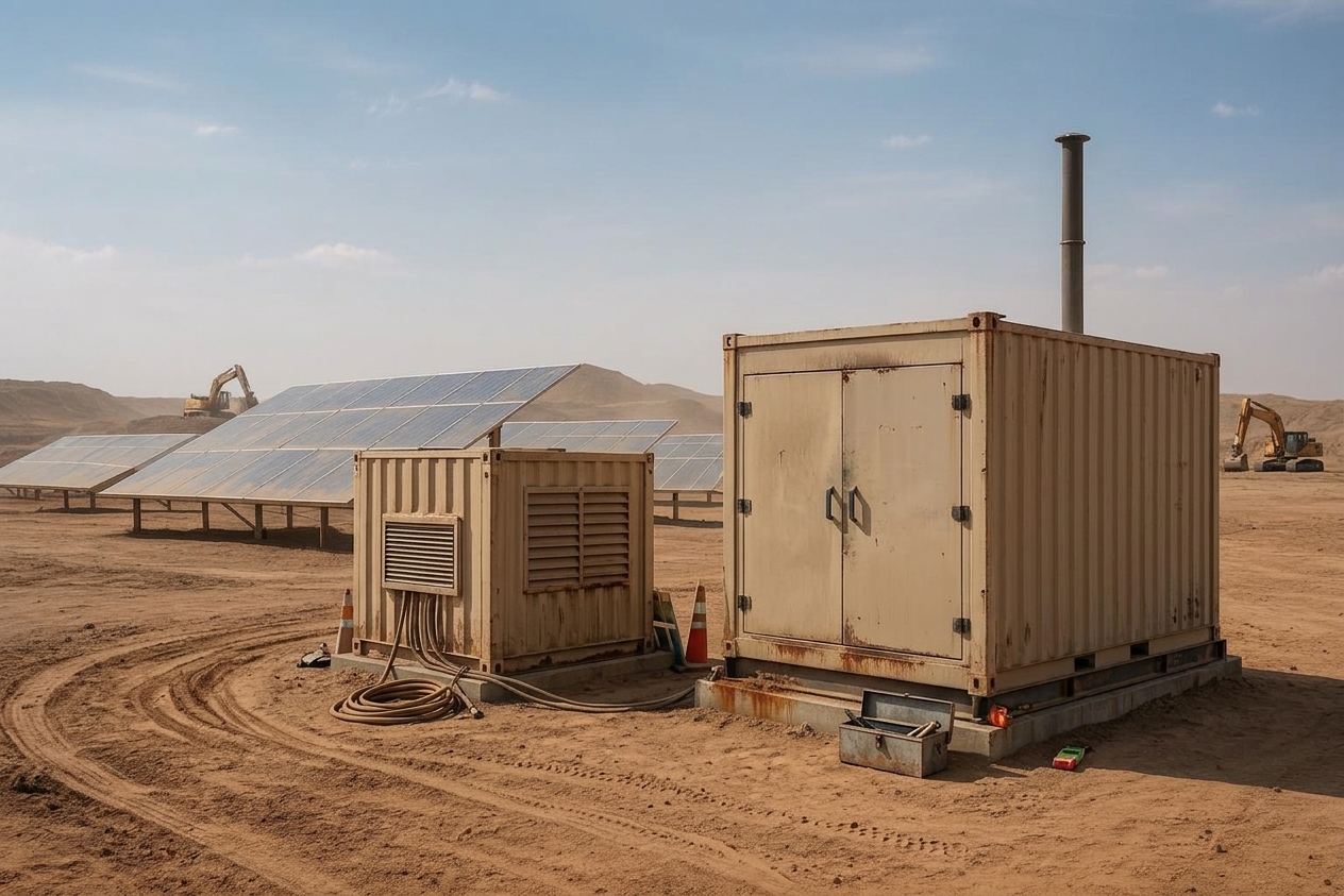
In off-grid industrial projects—mines, remote processing sites, island facilities, temporary construction power—PV + battery storage + diesel generation has become the standard setup.
And yet many EPCs see the same post-commissioning reality: the site added PV and a BESS, but diesel consumption doesn’t fall the way the model predicted.
That’s partly because industrial off-grid sites aren’t “steady” loads. They have sharp ramps, long run hours, and hard uptime requirements—so dispatch decisions show up quickly in both OPEX and asset life.
In practice, fuel savings in hybrid microgrids live or die on dispatch and controls.
The BESS is not just an energy container. It’s the flexibility layer that lets the EMS keep PV and generators in their efficient operating zones—if the dispatch logic is built around real load behavior and generator constraints.
This guide is for EPC contractors and system integrators designing or upgrading PV+BESS+diesel systems who want diesel reduction without sacrificing uptime.
Before you touch dispatch settings, align the roles of PV, the battery, and the genset—most fuel-saving failures start with role confusion.
Solar PV: lowest marginal cost energy (but not a firm power source)
PV generally provides the lowest marginal energy cost in an off-grid hybrid system. Its drawback isn’t price—it’s variability. Cloud transients and ramp rates can be harsh, especially when industrial loads aren’t smooth.
In dispatch terms: use PV first whenever it’s available, but don’t expect it to “hold the grid stable” on its own.
Battery storage (BESS): not “backup,” but the dispatch stabilizer
In hybrid systems, the BESS earns its keep by doing three jobs the generator is bad at:
absorbing fast PV ramps and load transients
preventing generator start/stop cycling
enforcing an SOC/reserve policy so the system stays stable during uncertainty
That’s why this matters: the battery is the flexibility layer that keeps PV and generators operating in their efficient zones. If you treat it as only a night-time backup, you’ll push the genset into the very operating modes that waste fuel and create maintenance headaches.
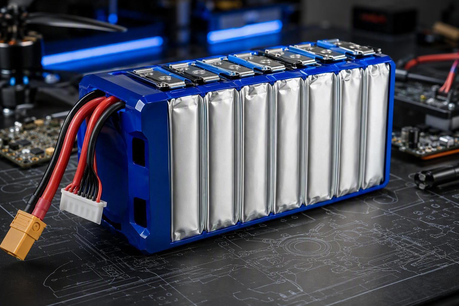
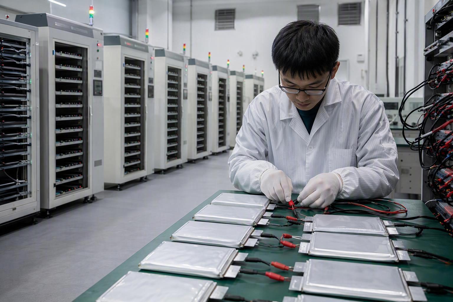
But this role also raises the bar for battery system engineering. In industrial microgrids, a BESS is routinely exposed to fast charge/discharge events (high C-rates), frequent partial cycles, and wide temperature swings.
For EPCs, battery selection shouldn’t be based on usable kWh alone. The BESS must support the power (kW) profile, thermal conditions, and communications/telemetry requirements that your EMS strategy depends on.
Cell chemistry, thermal management, and BMS controls determine whether the battery can deliver this balancing function reliably for years—without quietly shrinking usable capacity or triggering conservative derates.
Diesel generator: the reliability backstop (with efficiency constraints)
A genset is usually the most controllable source on site, but it’s not “infinitely efficient.” In most hybrid microgrids, it’s a reliability backstop—not the first-choice resource for fast peaking or minute-by-minute variability.
Extended low-load operation is a known failure mode (fuel waste + deposits). Many EPCs cite Caterpillar’s “The Impact of Generator Set Underloading” when aligning stakeholders on minimum-load constraints.
Dispatch implication: your EMS should either:
keep the genset above a minimum load threshold when it’s online, or
keep it offline and let PV + BESS do the balancing
Dispatch priorities for PV + BESS + diesel
A good hybrid microgrid dispatch strategy is less about clever math and more about respecting physical constraints:
PV is variable but cheap.
the battery is fast but has cycle-life constraints.
the genset is reliable but penalized by low-load operation and excessive starts/stops.
Most practical frameworks still boil down to a simple priority order:
PV serves load first
Battery absorbs the difference (charge on surplus, discharge on deficit)
Diesel runs only when required by reserve/SOC thresholds or a sustained deficit
You’ll see EMS implementations described as “load following” versus “cycle charging.” For EPC work, the label matters less than whether the control logic actually enforces the constraints above.
In commissioning data, the best systems look boring (in a good way):
the generator doesn’t start for every cloud
the battery doesn’t get deep-cycled unnecessarily
PV curtailment is minimized when storage headroom exists
A practical way to implement this priority stack is to think in three operating “modes” and switch between them based on what your site is actually seeing:
Stable solar hours: let PV carry the load, and charge the battery with any surplus. Keep the genset offline so the BESS can handle normal ramps and short load spikes.
Variable solar (fast ramps, passing clouds): protect your reserve first. Use a more conservative SOC policy, limit battery ramp/charge-discharge power as needed, and widen start/stop hysteresis so the genset doesn’t get pulled into short-cycling.
Prolonged low-solar (night, storms, multi-day poor irradiance): don’t wait for an emergency low-SOC event. Transition into a planned “recharge” window where the genset runs efficiently and, if there’s headroom, restores battery reserve for the next uncertainty period.
If you define these modes upfront, your commissioning tests become much simpler: you’re validating mode transitions and constraints—not improvising dispatch on-site.
If you want a shortcut for implementation and acceptance criteria, jump to the EPC checklist at the end—especially the items on reserve policy, fallback behavior, and genset minimum-load and hysteresis logic.
Three dispatch mistakes that increase diesel consumption
If you want a fast diagnostic, compare your logs to the expected operating pattern above—most cases where PV + BESS was installed but diesel didn’t drop map to one (or more) of the three dispatch mistakes below.
Mistake 1: “PV-first” without variability management → battery gets drained → generator short-cycles
A common commissioning trap is to hard-code “PV first” as if PV output is stable.
Here’s what usually happens:
PV ramps down quickly (cloud transient)
SOC drops faster than planned
the genset starts to protect reserve
PV returns and the system short-cycles
The fuel penalty isn’t only steady-state efficiency. It’s operational churn: starts, warm-up behavior, and unstable load sharing.
What to do instead:
set a minimum battery reserve to cover forecast uncertainty
enforce ramp-rate and power limits so the battery isn’t used as a “shock absorber with no limits”
use start/stop hysteresis (SOC_low to start, SOC_high to stop) so the genset doesn’t toggle on every transient
A practical operator takeaway is to design the EMS so PV and the BESS absorb routine variability—so the generator doesn’t get dragged into short-cycling behavior.
Mistake 2: SOC windows are set for “maximum energy,” not for lifespan + reserve
In many projects, the BESS is technically sized well—but the SOC logic makes it behave badly.
Typical problems:
charging too late (PV surplus occurs but EMS doesn’t prioritize charging)
discharging too early (SOC is low when you actually need reserve)
operating near extremes for long periods (higher degradation risk)
You’ll usually see it as: high PV curtailment around midday + generator hours at night + battery alarms or early capacity fade.
In other words, surplus PV is available when you should be charging, but the system doesn’t store it—then burns diesel later to cover the same energy.
From a battery-system engineering perspective, SOC operating windows should be set based on cell chemistry, warranty requirements, thermal design, and the site’s duty cycle. The goal isn’t maximum daily energy throughput. It’s a workable balance between usable energy, reserve availability, and lifecycle performance.
One integration detail we ask EPCs to verify early is the EMS ↔ PCS ↔ BMS interface. The EMS can only enforce an SOC policy if BMS telemetry, operating limits, and fault states are correctly surfaced to the EMS/PCS. When those interfaces are incomplete, systems often fall back to conservative derates that quietly increase diesel run time.
The right window is a control parameter—not a one-size-fits-all number.
If you want an internal reference on longevity-first battery handling (even though it’s not microgrid-specific), Herewin’s post on preventing LiFePO4 premature failure is a useful reminder that longevity is often won by avoiding extremes—not by chasing “100% SOC at all times.”
Mistake 3: The generator runs at low load because no minimum-load rule exists (or the set is oversized)
This is the most expensive mistake to ignore because it’s a silent diesel sink.
Gensets also have a “sweet spot” for fuel efficiency. If dispatch keeps a generator lightly loaded for long periods, fuel burn per delivered kWh rises—and maintenance headaches tend to show up sooner.
If the EMS starts the genset whenever SOC is low—without checking whether the current load can keep the genset in a healthy operating region—the generator can spend long periods lightly loaded.
Common triggers:
oversized genset relative to actual average load
no “minimum load” control (the generator is online “just in case,” idling at low load while the battery is underused)
What to do instead:
enforce a genset minimum-load threshold when online
when load is below the threshold, keep the genset off and use the BESS—or intentionally charge the battery to raise load (within battery limits)
Warning: “Running the generator more often” is not the same as “running it more efficiently.” Without minimum-load rules, more run hours can mean more fuel per delivered kWh.
What “good EMS control” should achieve
For EPCs, “good dispatch” should be testable—you should be able to verify it in commissioning logs.
Here are the outcomes worth specifying:
Low starts/stops (unless you’re intentionally running peaker-like)
High PV utilization (low curtailment when SOC headroom exists)
Generator stays above minimum load when online
Battery SOC stays inside an agreed window most of the time
Reserve is explicit (SOC floor or kW reserve)
Power quality is stable (frequency/voltage excursions are not “hidden” by nuisance alarms)
Think of it this way: the EMS isn’t “choosing which box makes power.” It’s deciding which asset absorbs variability—and whether the genset is protected from inefficient operation.
A simple OPEX sensitivity table EPCs can use in early design reviews
Below is an example template. Numbers are placeholders on purpose—use your site’s real values.
Input (Example assumption) | Why it matters |
|---|---|
Diesel price | Sets the value of each saved kWh |
Generator online hours | Direct proxy for fuel burn and maintenance |
Generator average load factor | Underloading increases fuel per kWh and deposit risk |
Starts/stops per day | Drives O&M cost and reliability risk |
Battery SOC operating window | Balances usable energy, reserve, and lifecycle |
The point of the table is not precision. It’s to force a design review conversation around the few parameters dispatch changes the most.
EPC checklist
Use this as a spec/commissioning checklist. Before commissioning, verify:
Generator minimum-load logic: a defined minimum load threshold for “genset online” mode
Start/stop hysteresis: clear SOC_low to start and SOC_high to stop (or an equivalent reserve-based policy)
Battery operating window: SOC limits aligned with chemistry, warranty, thermal design, and duty cycle
Power and ramp limits: enforceable charge/discharge kW limits and ramp-rate limits (not just in datasheets)
PV curtailment rules: curtailment is intentional and logged with reason codes
EMS ↔ PCS ↔ BMS integration: control points, telemetry, and fault states are defined; fallback behavior on comms loss is defined
Data logging & acceptance tests: exportable time-series data (PV kW, load kW, battery kW, SOC, genset kW, starts) and pass/fail criteria (e.g., max starts/day, minimum genset load factor)
In hybrid microgrids, diesel reduction depends on dispatch—not on adding more hardware
For EPCs, the winning architecture is not “more PV” or “more battery” in isolation.
It’s a control strategy that consumes PV first, uses the BESS as the variability buffer and reserve enforcer, and runs the generator only when thresholds demand it—while keeping it out of damaging low-load operation.
If you’re commissioning a PV+BESS+diesel site and want a battery-system-focused review, Herewin can support EPCs and system integrators as a battery system engineering partner for industrial energy storage applications—covering cell/chemistry selection, pack design constraints, BMS integration points, thermal management considerations, and validation/acceptance requirements.

 한국어
한국어  English
  Español
  Deutsch
  Français
  日本語
日本語  Русский
  Bahasa Indonesia
  ไทย
ไทย  العربية
  Português do Brasil
  Italiano
  Nederlands