
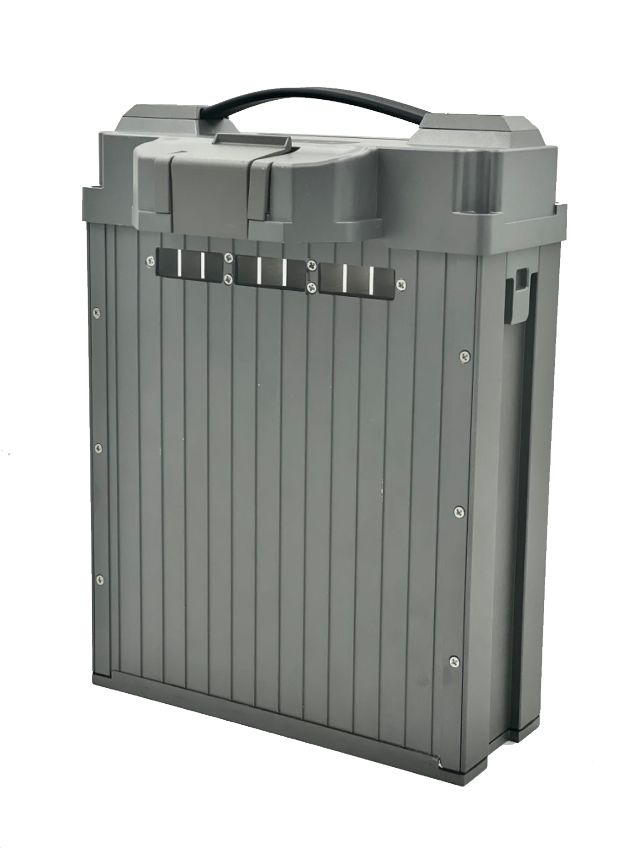
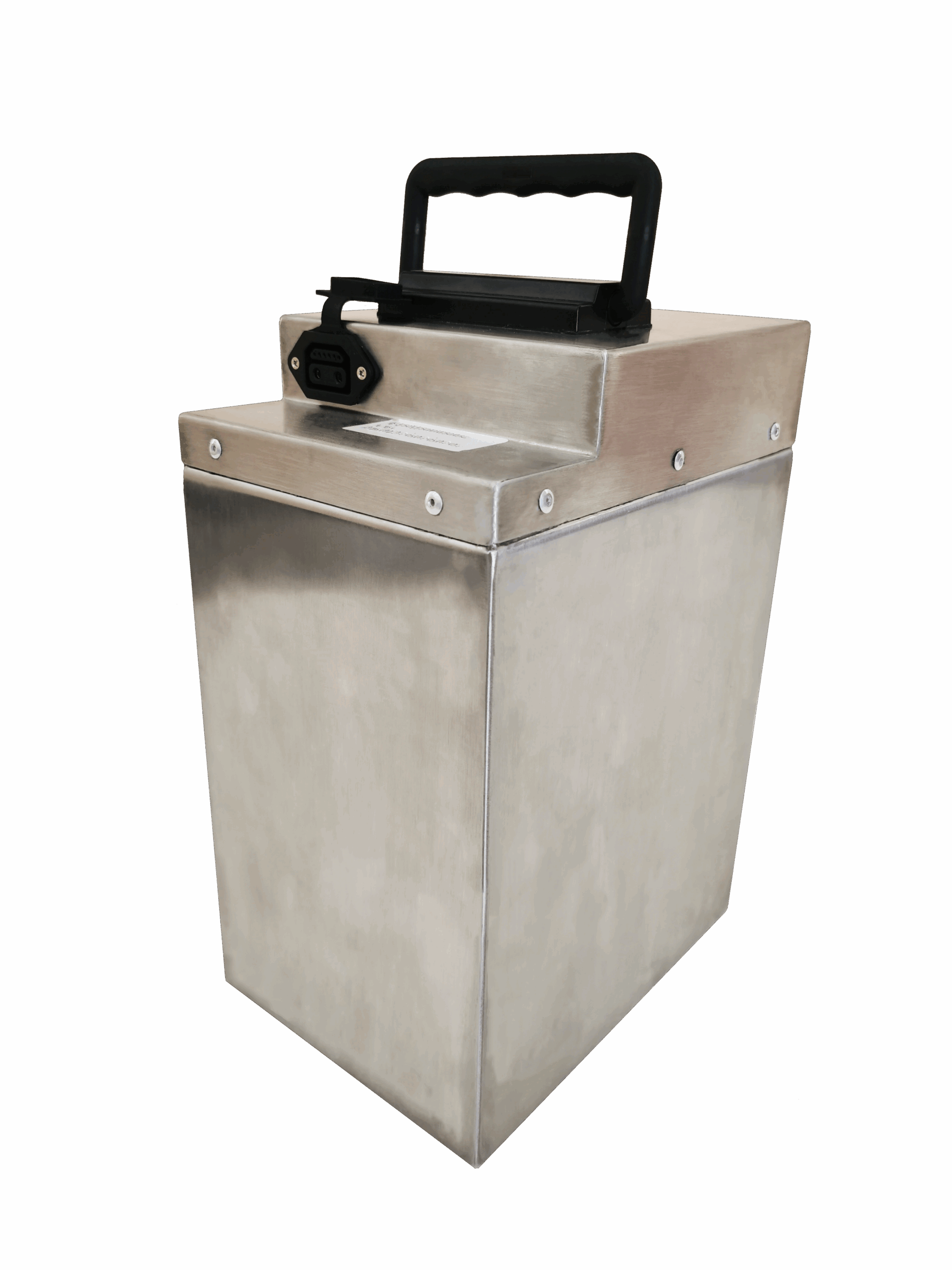




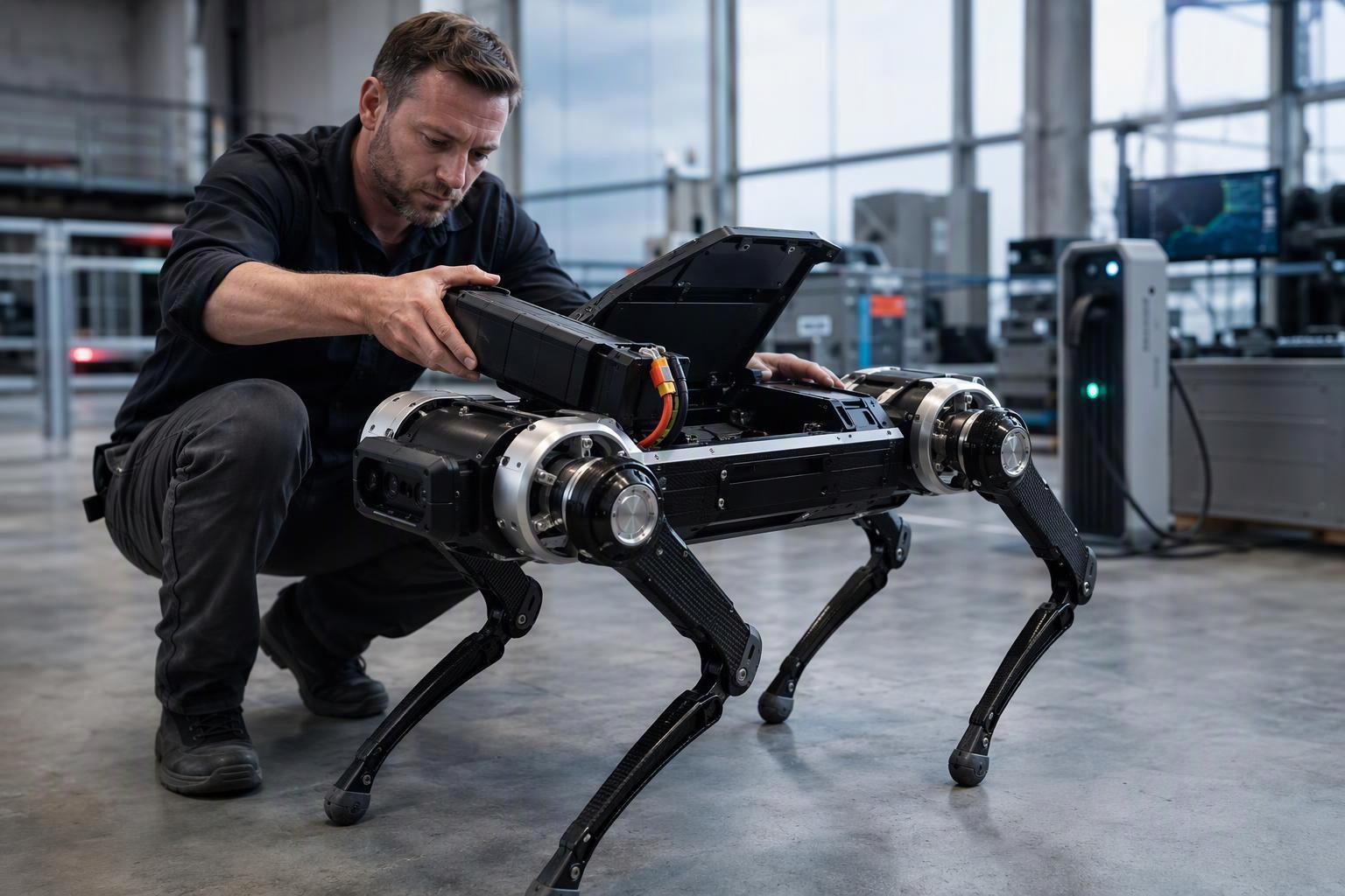
A robot can have correctly sized motors, a well-tuned controller and a healthy battery, and still trip undervoltage protection during a hard acceleration, a jump or a fast posture change. The cause may lie in the power supply rather than in the motor or controller itself. If the DC bus voltage falls below the drive’s undervoltage threshold for long enough, the drive may limit output or trip, even when the battery still has usable energy remaining.
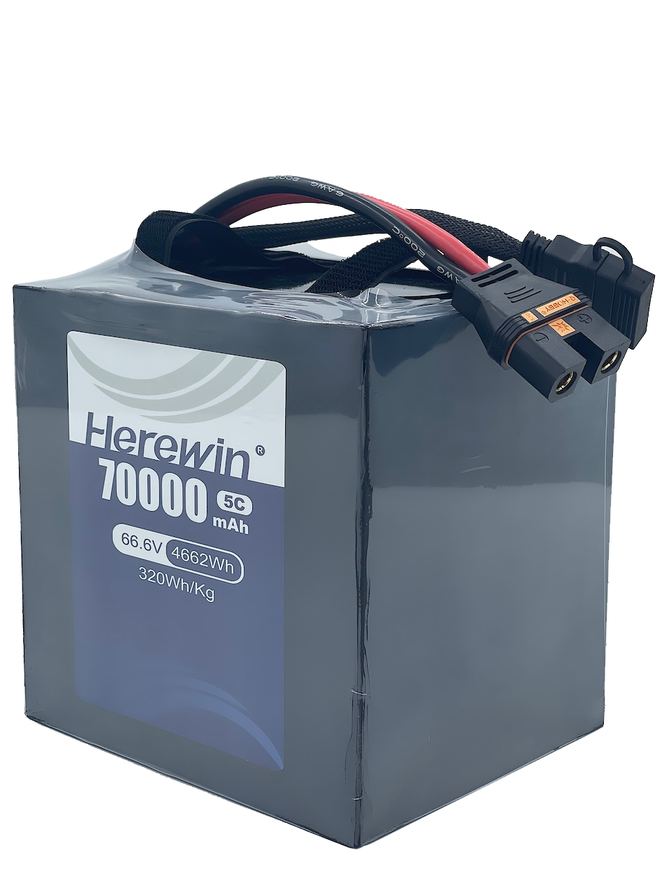
This mismatch is an important consideration when selecting batteries for dynamic robotic systems. Battery selection for a dynamic machine is not only a question of usable energy. Capacity and instantaneous power capability are different properties, measured under different conditions. A high-rate LiPo pack can be a suitable choice for a high-dynamics robot, but suitability depends on the pulse current profile, the continuous load, the thermal conditions and the architecture of the whole power system.
Why Dynamic Loads Change Battery Requirements
Sizing a robot battery from average power consumption answers the wrong question. Average power tells you how much energy a duty cycle consumes; it says nothing about whether the pack can hold voltage while the machine starts, accelerates, changes load or brakes. During those transitions the current demand can change within milliseconds, and the pack sees a sequence of pulses rather than a smooth draw.
Think of it as lifting rather than walking. A walker and a weightlifter can burn the same calories over a minute, but only one of them has to produce a large force in a fraction of a second, and that burst is what the power system has to survive.
What matters, then, is the shape of the pulse sequence: how large each peak is, how long it lasts, how often it repeats, and how much recovery time the pack gets between movements. A short pulse repeated with long gaps and the same pulse repeated back to back are different electrical and thermal events.
Operating condition | What to evaluate |
|---|---|
Startup and acceleration | Peak current and voltage dip |
Repeated dynamic movements | Pulse duration and recovery time |
Sustained operation under load | Continuous current and temperature rise |
Regenerative braking, if applicable | Charge acceptance and DC-bus architecture |
Regenerative braking deserves a separate caution. Not all braking current flows back into the battery. Where the energy goes depends on the drive, the DC bus, whether a brake chopper or resistor is present, and how much charge the pack can accept at that moment. In a multi-axis system with high-inertia loads, the DC bus can rise during deceleration, and the bus architecture — not the battery alone — determines whether that energy is absorbed, dissipated or allowed to trip an overvoltage threshold.
How Internal Resistance Affects Voltage Sag and Heat
Voltage sag under load is a common cause of undervoltage trips in high-power systems, but it is not the only possible cause. Connections, protection settings and drive thresholds can produce the same symptom. In a simplified equivalent model, a battery behaves as an ideal voltage source in series with an internal resistance. When current flows, the terminal voltage falls below the open-circuit voltage. The resistive voltage drop and the power loss are estimated as:
ΔV ≈ I × R
P loss = I² × R
Illustrative example, not a product specification. Assume a pack-level equivalent DC resistance of 5 mΩ under defined state-of-charge, temperature and pulse-duration conditions. At 300 A, the model predicts a 1.5 V drop and 450 W of loss during the pulse; at 10 mΩ, 3 V and 900 W.
These estimates hold only within that measurement boundary. External wiring and connectors add further drop, and pulse duration and repetition govern temperature rise. Actual performance should be verified under the intended operating conditions.
The first relationship explains why sag scales with current. The second explains why heat does not: doubling the current roughly quadruples the resistive loss, so a pulse that looks modest on a current trace can deposit substantially more heat than a steady draw of the same average value.
That heat matters twice over. Heat can accumulate across repeated events, reducing the available thermal margin and potentially accelerating degradation. As temperature and operating conditions change, the pack’s voltage response may also vary from one run to the next. And when the terminal voltage drops to the drive’s protection threshold, the system may limit power or shut down even though stored energy remains.
A second effect is worth knowing about. A drive trying to hold output power as bus voltage falls may pull more current, within its control strategy and current limits, which lowers the available margin further. Whether this happens depends on the operating point — one more reason to test at the real load profile rather than a single rated current.
The model has limits. Resistance must be the pack-level equivalent DCIR measured under defined conditions, not a single-cell figure — interconnects and connectors contribute, and the measurement timescale changes the answer. Voltage response also depends on state of charge, temperature, pulse duration and polarization. Use the IR picture to understand the mechanism, then verify it on the actual pack. A single 5 mΩ or 10 mΩ assumption illustrates the principle; it is not a substitute for pack-level data across the resistance range you might reasonably encounter.
Testing should also cover the cold end of the range. At the lowest expected operating temperature, higher internal resistance can deepen the sag and cut available power, so a pack that clears its voltage margin at 25 °C may not clear it on a cold first start, before self-heating has any chance to act.
C-Rate, Peak Current and Continuous Discharge
A datasheet that advertises a high discharge rate does not by itself prove that a pack will avoid undervoltage in a specific machine. The rating is a starting filter, not a performance guarantee.
The conversion between C-rate and current is straightforward:
I = C rate × Q
where Q is capacity in Ah. A 10 Ah pack rated at 20C corresponds to 200 A. That arithmetic is easy; interpreting the rating is not, because three different figures are often conflated:
Continuous discharge rating — the current a pack is rated to deliver under specified operating and thermal conditions, subject to its voltage limits and protection requirements.
Peak discharge rating — a short-term current allowed only for a stated duration and under stated starting conditions.
Pulse performance — the voltage and thermal response the pack actually exhibits at a given pulse width, interval, state of charge and temperature.
For an OEM reviewing a specification, the useful questions are concrete: how long does the peak last, how many times is it repeated, what minimum voltage is permitted at the load, and is the temperature rise acceptable under continuous operation? A peak figure quoted without duration, rest period, starting SOC and temperature cannot be converted into a duty cycle. Rate ranges lifted from consumer marketing material should stay out of an engineering evaluation unless they are tied to a specific cell model, manufacturer data and test conditions.
Why High-Rate LiPo Can Be a Good Fit for Robotics
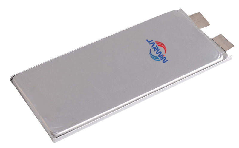
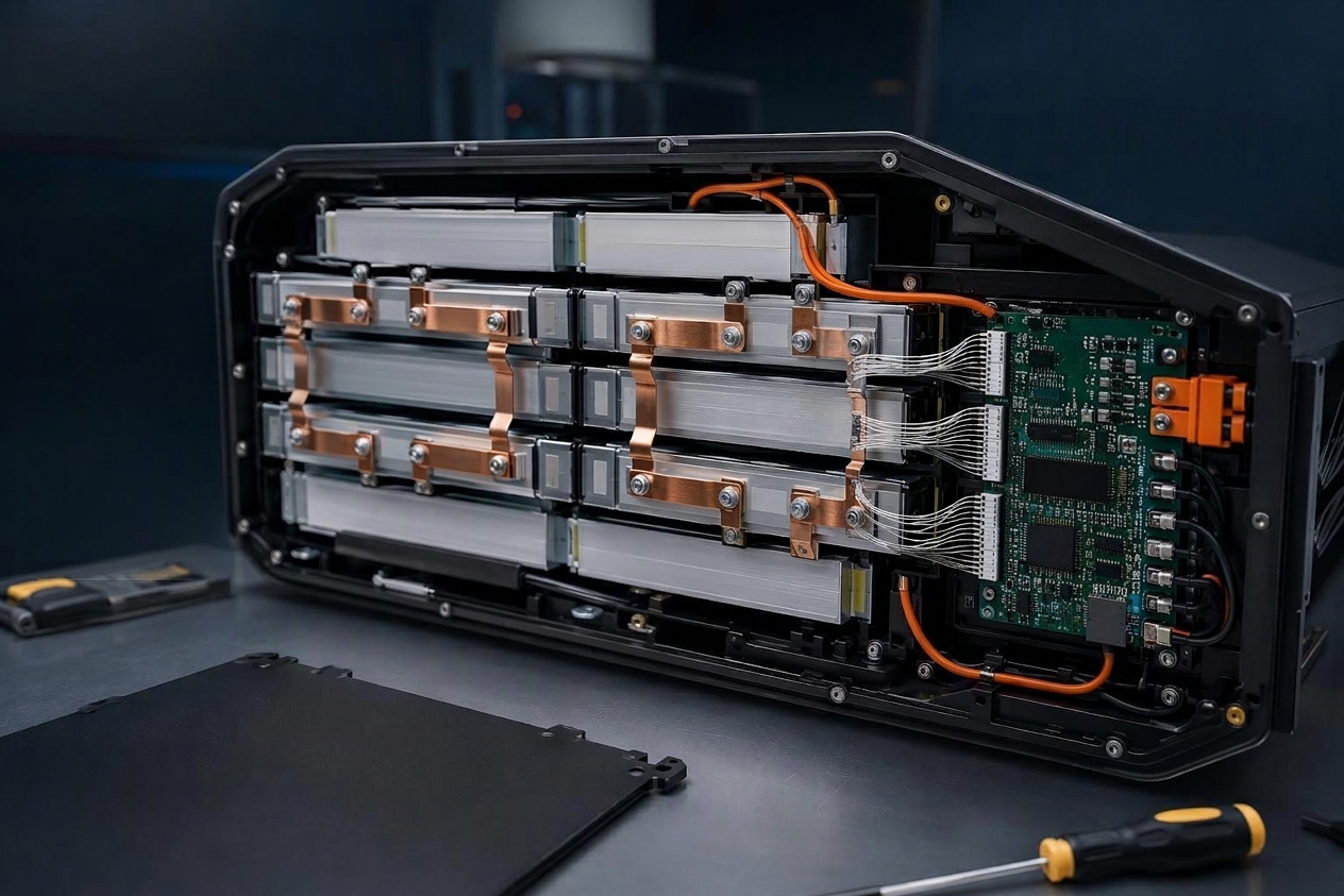
With the failure mechanism established, the case for high-rate LiPo becomes specific rather than general. A high-rate LiPo pouch pack can be worth evaluating when a robot requires substantial short-duration current and has strict mass or packaging constraints. Whether it offers an advantage depends on the specific cells, pack construction and system-level requirements. The relevant advantages are engineering outcomes, not claims about a cell format:
High current delivery. Appropriately designed high-rate cells can support large short-duration currents, which is what a jump, a sprint start or a rapid posture change demands.
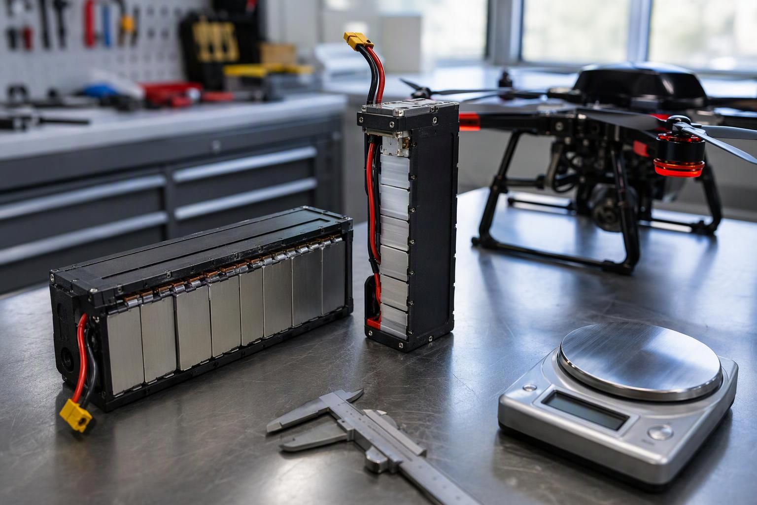
Pack design flexibility. The pouch format allows cells to be arranged around the space a robot actually has, which matters when the battery bay is shaped by joints, frames and electronics rather than by a standard enclosure.
Power-to-weight considerations. When both instantaneous output and mass are constrained — as they are in legged and humanoid platforms — a high-rate LiPo pack is worth evaluating against alternatives.
Application-specific integration. Cell capability becomes pack performance only through the right series–parallel configuration, current path, connection method and protection strategy.
A pouch format does not by itself guarantee low internal resistance, low temperature rise or higher safety. Electrode design, tab configuration, cell chemistry, manufacturing quality and overall pack design jointly determine what the pack delivers.
Those advantages come with a boundary, though, and it sits on the other side of the same list. If an application prioritises long run time, energy density, cycle life, mechanical ruggedness or low maintenance cost, a high-rate LiPo pack is not the obvious starting point; it has to earn its place against other cell options. The useful question is rarely whether LiPo is better, but under which conditions it is worth considering.
LiPo vs. Cylindrical Cells: Which Design Fits the Application?
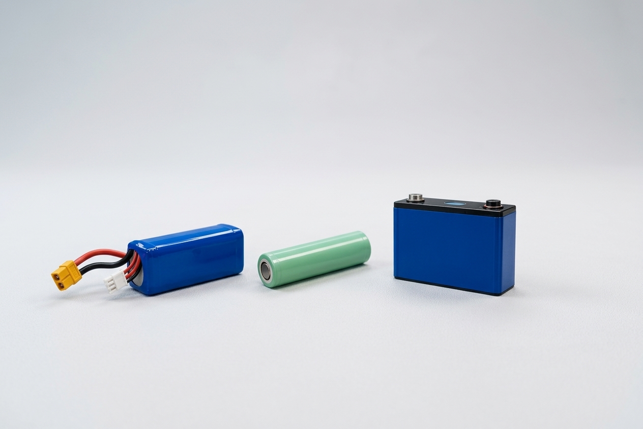
Because that answer is application-specific, the comparison has to rest on evaluation factors rather than on format names. Note, too, that “cylindrical” covers two quite different performance classes: standard-power cells built for energy and cost, and high-rate cylindrical cells built for current. Lumping them into one column hides the choice that matters most.
The table below is a framework for that comparison, not a ranking. Actual discharge capability, DC resistance, energy density and cycle life depend on the specific cell, pack design and test conditions.
Evaluation factor | High-rate LiPo pouch | Standard-power cylindrical cells | High-rate cylindrical cells |
|---|---|---|---|
Continuous discharge | Verify continuous current rating and temperature rise over the intended duty cycle | Check continuous-current limits and thermal performance | Check continuous-current limits and thermal performance |
Peak and pulse discharge | Evaluate peak current, pulse duration and voltage sag | Confirm that the selected cell supports the required pulse load | Evaluate pulse capability under the same load and test conditions |
Pack-level DC resistance | Verify DCIR and voltage response under defined SOC, temperature and pulse conditions | Check cell resistance and account for interconnects and pack configuration | Check cell resistance and account for interconnects and pack configuration |
Energy density and pack mass | Assess usable energy and mass at the required power level | Compare cell energy density with the resulting pack-level mass and volume | Compare cell energy density with the resulting pack-level mass and volume |
サイクル寿命 | Validate under the intended load profile, temperature and depth of discharge | Assess cycle-life data under comparable operating conditions | Assess cycle-life data under comparable operating conditions |
Packaging and integration | Consider pouch support, thickness changes, current paths and thermal management | Account for cylindrical geometry, interconnections and module layout | Account for cylindrical geometry, interconnections and module layout |
Two common shortcuts are unreliable. Assigning cylindrical cells to AGVs and LiPo packs to humanoid robots based on robot type alone overlooks the actual load profile. Likewise, treating all cylindrical cells as low-rate options ignores the capabilities of high-rate models. High-rate cylindrical cells can also serve dynamic loads, while a LiPo pouch pack still needs to demonstrate adequate continuous-load capability and cycle life at the pack level.
What holds up is a narrower rule. Robots dominated by short, high-current bursts may justify evaluating high-rate LiPo packs; applications that prioritise sustained operation, cycle life, mechanical robustness or maintenance cost may favour other formats. Either way, the comparison should rest on the actual load profile, operating environment and pack-level performance, not on the robot category.
What to Validate Before Integrating a High-Power Battery Pack
The technical picture becomes a procurement decision at the point where an OEM has to approve a pack for integration. The checklist below is an evaluation method to bring into a design review or a supplier conversation; it describes what should be established, not services that any particular supplier has already performed.
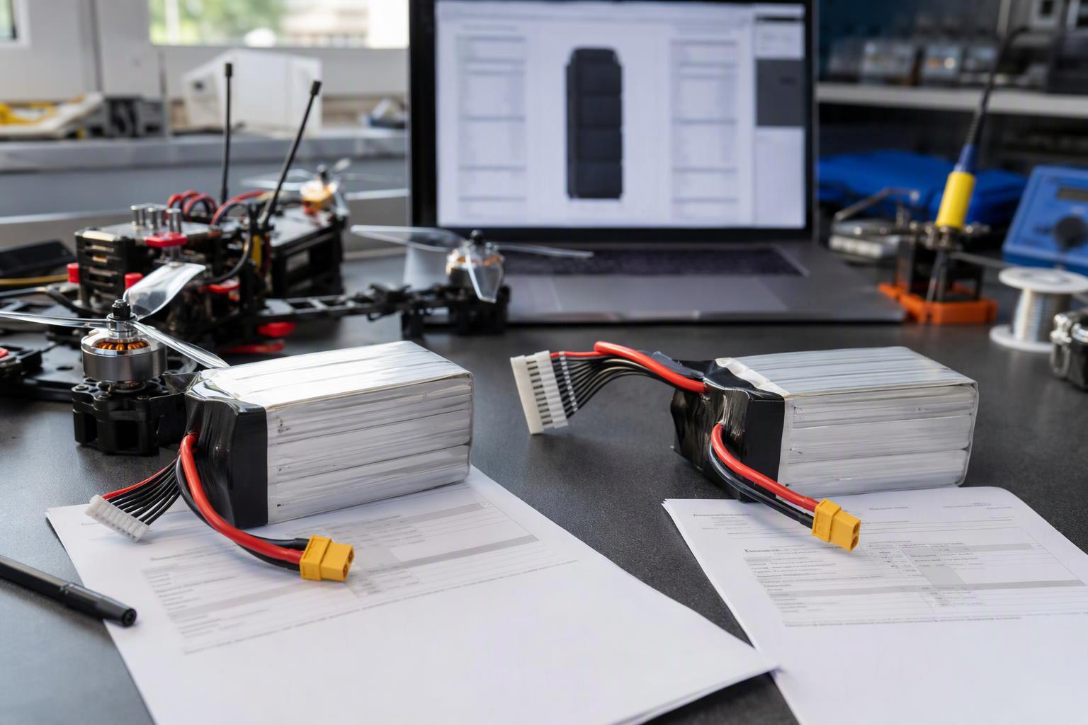
Load profile. Define peak current, pulse duration, pulse interval, continuous load and the actual motion cycle. A profile based on representative duty cycles is more useful than a single worst-case number.
Voltage and resistance. Measure voltage response at the target state of charge, operating temperature and pulse conditions. Confirm the minimum bus voltage required by the drives, and request the DCIR measurement conditions alongside the reported value.
Thermal performance. Measure temperature rise under repeated movements and sustained load, not only during a single peak; heat accumulates, and the relevant question is the margin at the end of a cycle. Repeat the voltage-margin test at the lowest expected operating temperature, where a warm-bench result no longer describes the machine.
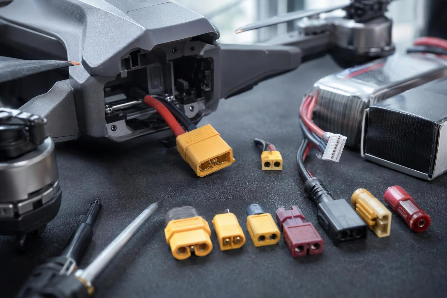
Pack and system integration. Confirm BMS protection thresholds, wiring, connectors, current paths, mechanical retention, charging requirements and the regenerative-braking strategy. Pack-level voltage limits and individual-cell undervoltage thresholds may respond differently under load, so both protection behaviors need to be verified. For pouch cells, confirm that mechanical support and allowance for thickness changes meet the cell manufacturer’s specifications. Cell-level monitoring, charge and discharge limits, and protection settings should match the selected cell and pack design. Under high current, voltage sag can trigger undervoltage protection even when substantial usable capacity remains. Low-temperature, high-temperature and prolonged high-rate operation should all be included in the validation plan.
Lifecycle requirements. Evaluate capacity fade, impedance growth, maintenance needs and replacement cost over the target duty cycle, rather than relying only on beginning-of-life performance.
For OEM teams, battery selection should go beyond nominal capacity and discharge-rate ratings. A reliable evaluation starts with the machine’s load profile, voltage limits, thermal constraints and intended duty cycle. These requirements should be defined before comparing candidate cells or approving a pack for integration.
Match Battery Performance to the Real Load
When a high-dynamics manoeuvre ends in an undervoltage trip, the battery may still have usable energy remaining. The immediate limitation may be its ability to maintain voltage under peak demand, rather than its nominal capacity alone — a property of the load profile, not of the label on the datasheet. Picking a higher C-rate rarely fixes that on its own.
A high-rate LiPo pack can be the right answer, but the choice should rest on a combined assessment of the real load, voltage margin, temperature rise, mass, cycle life and pack integration. An evaluation that starts from the load profile, voltage limits, space constraints and duty cycle will narrow the field faster than a datasheet comparison.
If you are evaluating a battery pack for a high-power robotic platform, you can contact our team to discuss your application requirements.


 日本語
 English
 Español
 한국어
 Deutsch
 Français
 Русский
 Bahasa Indonesia
 ไทย
 العربية
 Português do Brasil
 Italiano
 Nederlands