


Close-proximity nacelle inspections subject UAV power systems and BMS electronics to high-intensity electromagnetic fields. Engineering failure in these environments often manifests as premature protection trips during mid-hover or telemetry loss at critical blade-root alignments. These are not merely operational glitches; they represent a fundamental breach of EMI resilience that leads to repeated sorties, lost inspection minutes, and compromised mission uptime.
The following analysis outlines the technical requirements for EMI-resistant power systems, supported by a nacelle immunity validation protocol (bench-top and in-situ) focusing on current sampling accuracy, dynamic signal integrity, and signal-to-noise ratios (SNR).
Why Renewable Energy Inspections Demand Specialized Drone Batteries
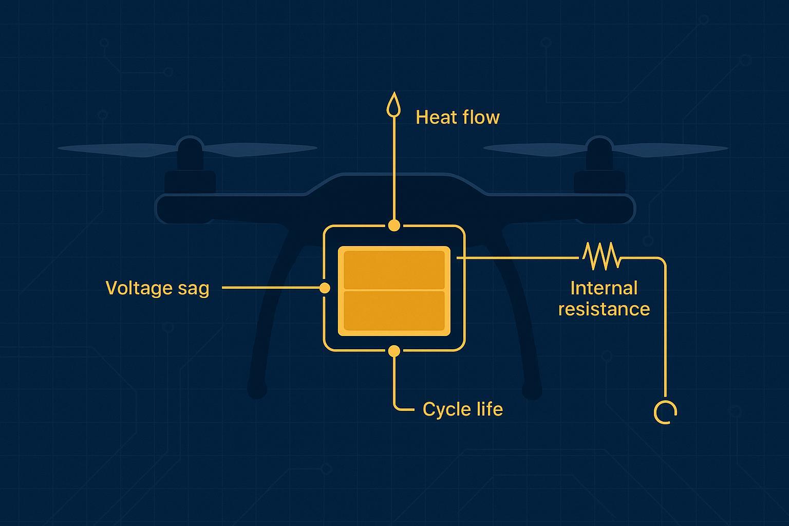
Industrial O&M flights differ from cinematic capture. They involve long duty cycles near high-power generators, converters, and cabling, with strong power-frequency magnetic fields and broadband switching noise. Batteries aren’t just energy tanks here; they’re active, safety-critical systems that must measure current and temperature accurately while delivering high burst power without false trips.
Unique Operational Challenges in Wind, Solar, and Offshore Environments
Wind: Near-field magnetic flux around generators and high-current busbars can corrupt current sensing and induce protection misfires. Gusts demand sudden thrust steps, spiking discharge rates.
Solar: High radiative heat loads flatten discharge curves and accelerate thermal runaway risks if detection lags; long grids demand coverage efficiency, not just minutes of flight.
Offshore: Salt fog and humidity attack connectors and PCBAs; corrosion raises impedance, worsens noise susceptibility, and compromises seals.
From Energy Storage to Mission-Critical Power Infrastructure
Treat the inspection battery as infrastructure, not a consumable. It must preserve bus voltage stability under step loads, maintain accurate telemetry for SOH/DCIR, and resist EMI that would otherwise trigger spurious overcurrent or undervoltage protections. The result isn’t just longer airtime—it’s fewer aborted missions and better ROI.
Drone Platform Power Requirements for Industrial Inspections
Power Architecture of Multi-Rotor and VTOL Inspection Platforms
Multi-rotors demand high instantaneous currents during hover, gust rejection, and precise positioning. VTOLs mix hover segments with efficient cruise, forcing the pack to handle wide dynamic ranges and transitions. Both architectures expose the battery to PWM-rich environments from ESCs, which can couple into measurement chains.
Voltage Stability and High-Current Discharge for Mission Payloads
Thermal cameras, radiometric sensors, and LiDAR spikes can coincide with thrust steps. The battery must sustain high current without sagging the mother bus below flight controller brownout thresholds. Engineering levers include low-impedance interconnects, appropriate cell chemistry selection, and DCIR-aware power budgeting. Accurate current and voltage telemetry is non-negotiable—noise-induced errors propagate into SOC/SOH estimates and can force premature landings.
EMI Resilience for Close-Proximity Wind Turbine Inspections
Nacelles combine 50/60 Hz fundamentals with harmonics and wideband EMI from converters. The coupling paths are conductive (harnesses, grounds), radiative (RF), and magnetic (near-field) — all of which can stress a BMS.
The Induced Current Risk: Why Conventional BMS Fails in High-Voltage Environments
Conventional shunt + current-sense amplifier (CSA) architectures are accurate and efficient. But in high-voltage, PWM-heavy environments, they can lose measurement integrity due to two primary coupling mechanisms:
Common-mode dv/dt and PWM edge noise from ESCs and DC/DC converters can leak into the CSA front end and corrupt ADC samples. TI’s INA241 application brief on enhanced PWM-rejection current sensing is a useful reference for how these transients show up in real measurements.
Power-frequency magnetic induction (50/60 Hz fundamentals and harmonics) can drive unwanted currents in the shunt/sense-lead loop area, adding offset and ripple. TI also notes that filtering choices can unintentionally degrade CMRR and settling; see TI’s SLYA042 note on input resistance error and filter trade-offs for CSAs.
For setting test targets, industrial immunity references commonly cite IEC 61000-4-3 radiated RF immunity sweeps across roughly 80 MHz–6 GHz (up to 30 V/m for harsh sites) and IEC 61000-4-8 power-frequency magnetic immunity evaluations up to around 30 A/m for industrial machinery. Intertek’s overview of on-site (in-situ) EMC/EMI testing for large machinery is a practical summary of how these levels are discussed for industrial environments. Use them as engineering guideposts when you define — and later validate — a wind turbine inspection battery’s EMI immunity goals.
Engineering Defense: Hardware Shielding and Adaptive Filtering Algorithms
EMI resilience requires a layered defense architecture spanning physical shielding, signal integrity control, and firmware-level filtering. The objective is to maintain measurement integrity and protection stability under high electromagnetic stress conditions.
1. Physical Layer: Shielding and Enclosure
The BMS should be enclosed in a continuous conductive housing to attenuate radiated electromagnetic interference. A properly implemented Faraday enclosure reduces RF coupling from nacelle generators and power electronics.
The enclosure grounding strategy should follow a single-point bonding scheme to avoid ground loops. In environments dominated by power-frequency magnetic fields, additional localized shielding using high-permeability materials (e.g., mu-metal or soft iron) may be required to reduce magnetic coupling into sensitive measurement loops. Faraday enclosure implementation must also balance EMI attenuation with thermal dissipation requirements to preserve high-current discharge stability.
2. Electrical Layer: Signal Integrity and Measurement Chain Design
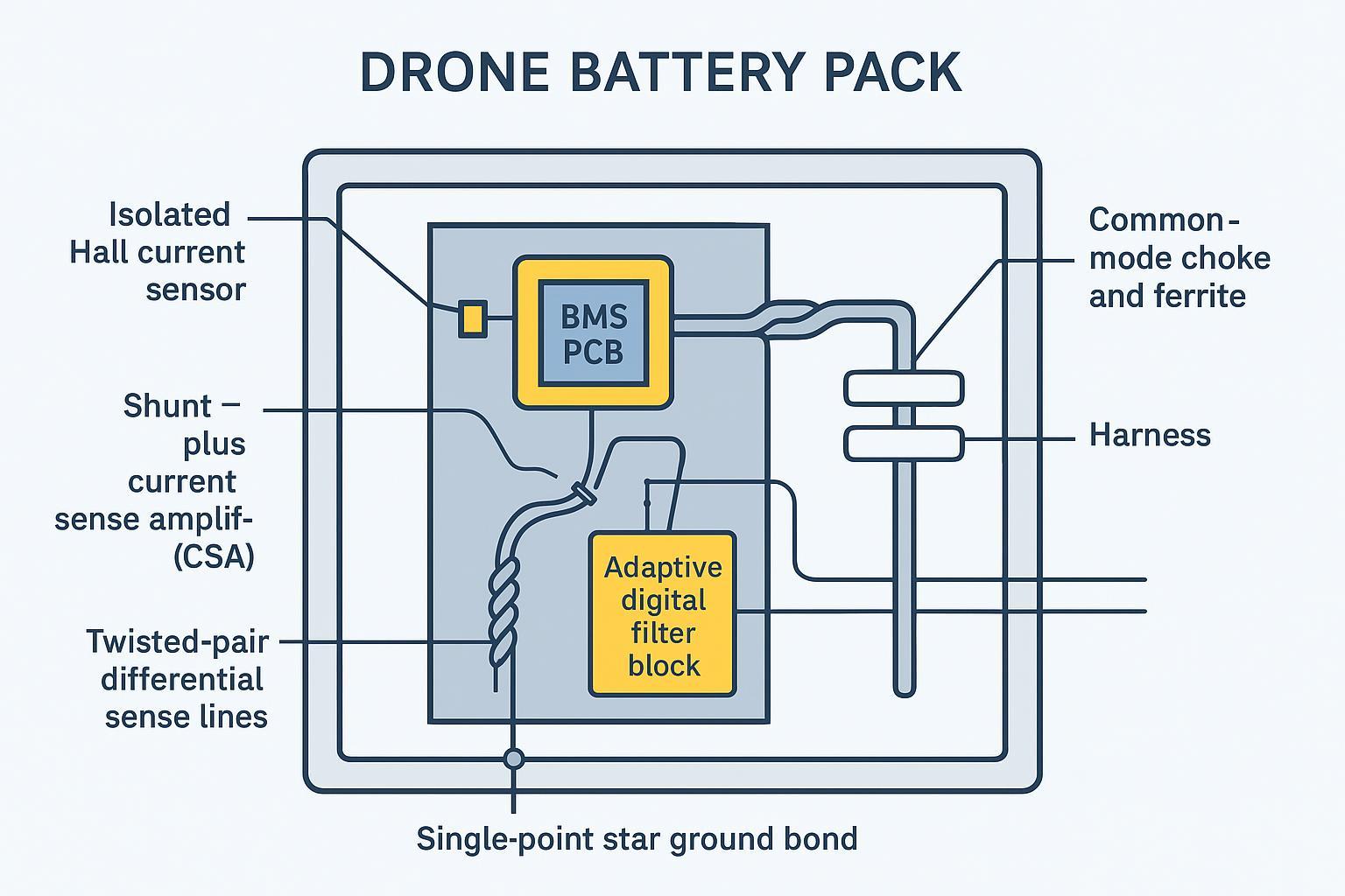
The measurement chain must be designed to minimize susceptibility to conducted and radiated interference. In high-flux environments, isolated Hall-effect sensors or current transformers are preferred on the main bus to decouple measurement from high-voltage transients.
Where shunt-based sensing is required, the layout must minimize loop area using Kelvin connections and tightly coupled differential routing. Sense lines should be implemented as twisted pairs with appropriate shielding termination.
The analog front end should incorporate input-stage RC filtering placed close to the current-sense amplifier. Component selection must balance noise rejection and bandwidth to preserve dynamic response under PWM switching conditions. Devices with enhanced PWM rejection characteristics should be selected to maintain stable sampling under high dv/dt environments.
3. Digital Layer: Firmware Filtering and Protection Logic
Firmware must implement filtering and decision logic to stabilize measurements under transient interference conditions. Its efficacy is constrained by upstream signal integrity, and software filtering cannot fully compensate for hardware-level sampling saturation under severe EMI. This includes oversampling and decimation, low-pass filtering (IIR/FIR), and adaptive notch filtering around known interference frequencies.
Protection logic should incorporate temporal filtering, voting mechanisms, and hysteresis to prevent transient disturbances from triggering false protection events. The system response must remain deterministic and repeatable under identical interference profiles.
Validation Framework & Acceptance Criteria for EMI Resilience
Acceptance criteria
A wind turbine inspection battery must demonstrate EMI resilience with pass/fail outcomes aligned to IEC 61000-4-3 and IEC 61000-4-8 style domains.
Test domain | Reference practice | Target levels (guide) | Pass/Fail acceptance |
|---|---|---|---|
Radiated RF immunity | IEC 61000-4-3 style sweep, dual polarization | 10–30 V/m, 80 MHz–6 GHz | Must demonstrate no false trips; current-sampling error stays within acceptable limits; SOH/DCIR telemetry remains stable |
Power-frequency magnetic | IEC 61000-4-8 axes X/Y/Z | up to ~30 A/m @ 50/60 Hz | Must demonstrate no resets; current-sampling error stays within acceptable limits; no protection misfires |
Conducted susceptibility | PWM fundamental + harmonics injection | per platform PWM (e.g., 8–32 kHz) | Must demonstrate no spurious overcurrent/undervoltage trips; bounded ripple and stable current measurement |
Firmware robustness | Filter set A/B with logs | Must demonstrate a statistically lower false-trip rate under identical interference profiles |
Validation approach
EMI validation must demonstrate coverage across all relevant interference modes and deployment conditions.
The system must be validated against:
Radiated RF exposure
Power-frequency magnetic field exposure
Conducted interference from PWM switching
Evidence must include both controlled bench testing and in-situ nacelle proximity validation, using consistent instrumentation, identical protection thresholds, and deployment-equivalent configurations.Validation results must confirm stable current measurement, consistent protection behavior, and repeatable system response under all tested interference conditions.
Comparative data
Comparative testing between a standard non-isolated shunt-based BMS and the interference-hardened architecture defined above yielded the following results:
Under controlled comparative conditions, an interference-hardened architecture using galvanic isolation, shielded twisted-pair sense routing, and a star-bonded metal enclosure, combined with a Hall sensor on the main bus, demonstrated measurable gains in signal integrity.
Bench-top sweep: 80 MHz–1 GHz at 20 V/m; current-sampling error reduced from 5.8% to 0.65% after shielding and sensor optimization.
In-situ nacelle proximity: spurious protection trip rate reduced from 8.2% to <0.15%.
注: This level of hardware sampling precision (0.65% error) provides the essential physical foundation for high-accuracy SOC/SOH algorithms (within ±3%), ensuring reliable telemetry and mission planning even in extreme EMI environments.
Procurement Checklist for EMI-Resilient Inspection Batteries
Procurement requirements must be defined as evidence-based qualification criteria.
Vendors must provide:
Radiated and magnetic immunity test reports aligned with IEC 61000-4-3 and IEC 61000-4-8 style domains, including both bench and in-situ validation.
Exportable telemetry logs (current, voltage, temperature, and SOH/DCIR where applicable) covering the exact interference conditions used during qualification.
Complete protection trigger records with timestamped events and configuration/version traceability.
Explicit verification coverage for radiated EMI, power-frequency magnetic fields, and conducted PWM interference.
Qualification failure conditions include:
Any false protection trips under defined EMI test conditions.
Unstable, non-repeatable, or interference-sensitive current sampling that compromises SOC/SOH estimation.
Missing or incomplete validation evidence for any required interference domain.
References & Technical Sources
IEC 61000-4-3 / 61000-4-8 (EMI immunity standards)
RTCA DO-160 Section 20 (EMI/EMC test practices)
Intertek (in-situ EMC/EMI testing guidance)
Keysight (EMI testing overview)
Next steps
Ensuring mission continuity requires site-specific EMI baseline assessments and validation against the acceptance criteria above. For specialized engineering support to evaluate power system resilience against specific flight envelopes, technical consultation via a professional engineering channel is recommended.
For consultation requests and supporting materials, use the Herewin engineering channel.