


If your UAV program has ever passed lab qualification but still produced field failures—unstable thrust under payload, unexplained voltage sag, endurance shortfalls, or “sudden battery cutoffs”—you’ve seen the same procurement trap repeat: a high C-rating is treated as the proxy for mission reliability.
It isn’t. A C-rating is one parameter in a much larger system. In real operations, stability is governed by what happens when dynamic current transients hit a multi-cell pack that’s warming up, aging, and interacting with the ESC + motor + payload stack. That’s where weak-cell behavior, resistance dispersion, and protection logic turn “high C” into a false sense of safety.
This article is written for UAV OEM engineering teams and technical procurement who need a decision-stage answer: how to qualify a battery pack supplier so real missions match your design intent.
Why lab-tested drone batteries still fail in real missions
A lab test often evaluates a battery in isolation, under controlled ambient conditions, with a simplified discharge profile. A mission doesn’t.
In field deployments, failures usually show up as system behavior, not a neat “battery failed” label:
Unstable thrust under payload (throttle feels inconsistent; the aircraft hunts under load)
Unexpected voltage sag on takeoff, gust recovery, or aggressive maneuvers
Reduced endurance vs. design spec, even when nominal capacity matches
Sudden cutoff events (a BMS cutoff or low-voltage protection behavior) despite remaining energy
These are symptoms of a battery that’s technically capable of high peak current but unable to deliver synchronized, stable power across all cells under dynamic conditions.
Why laboratory testing doesn’t reflect UAV reality
Most “passes spec” lab programs miss at least one of these gaps:
Static load vs. dynamic mission profile
UAV power demand is transient by design: takeoff, wind correction, altitude changes, payload actuation, and fast throttle ramps. A constant-current discharge isn’t a proxy for that.No thermal-electrical coupling
High current causes heat. Heat changes resistance. Resistance changes sag. The feedback loop matters.Insufficient system-level validation
The battery does not operate alone. A pack that looks fine on a cycler can behave differently once it’s driving your ESC and motors with real ramp rates and real protection logic.
A credible qualification program treats validation as a stack test, not a cell spec review.
Drone battery selection mistakes: treating C-rating as a reliability proxy
C-rating is easy to compare, easy to put into a datasheet, and easy for procurement to turn into a rule like “higher = safer.” That bias is expensive.
What C-rating actually measures (and what it doesn’t)
At a basic level, C-rating is a current multiple of capacity:
Continuous C-rating: what current the pack can sustain (thermally and electrically) for a defined duration without unacceptable degradation.
Burst/pulse C-rating: a short-term peak current capability for transients.
What C-rating does not directly guarantee:
stable voltage under rapid throttle changes
synchronized cell behavior inside a multi-cell pack
low dispersion in internal resistance (DCIR) across cells
protection behavior that aligns with your propulsion system
If you want a framework for sizing capacity and C-rating with real operational margins (instead of “pick the highest C”), Herewin’s internal guide on balancing capacity and C-rating to optimize TCO is a useful reference.
Why high C-rating becomes misleading in UAV systems
A high number can hide the assumption that causes most qualification failures:
Higher discharge capability does not guarantee system stability under dynamic load. Why?
Oversimplified performance assumption: “If peak current is covered, the mission is covered.” Not true when sag and cell dispersion dominate.
Procurement bias toward “higher = safer” logic: High C feels like extra margin, but it may be buying peak current you don’t need while ignoring consistency you do.
Marketing-driven specification distortion: Burst ratings are easier to inflate than long-duration stability metrics (temperature rise rate, DCIR distribution, cycle life under your mission profile).
C-rating is a necessary input. It’s not a qualification decision.
The missing variable: cell consistency
If you’ve ever seen a pack that looks great on average but behaves badly in flight, it’s usually because “average spec” hides dispersion.
What consistency means in multi-cell UAV packs
In a multi-cell pack, consistency means the cells behave like a synchronized set:
Inter-cell electrical uniformity (capacity, resistance, voltage behavior)
Thermal behavior alignment (cells heat at similar rates under the same current)
Degradation synchronization (cells age together instead of diverging)
A pack with inconsistent cells becomes weakest-cell limited—and that’s a deterministic failure mode in UAV operations.
The consistency metrics that matter in OEM qualification
You can’t manage what you don’t measure. For UAV packs, the practical cell-level metrics are (often called cell matching metrics in supplier qualification):
Capacity deviation (how far the weakest cell is from the strongest)
Internal resistance (IR / DCIR) variation (the spread, not just the average)
Voltage alignment and drift (delta under load and after rest)
Self-discharge rate (how fast cells drift during storage between missions)
These should be validated at the cell level and then re-checked after pack assembly and formation.
How inconsistency breaks real UAV performance
Field failures are not mysterious when you write the mechanism down.
1.Capacity mismatch reduces usable energy
In a series pack, the weakest cell defines the usable window.
Even if the pack’s average capacity looks correct, the lowest-capacity cell reaches the low-voltage threshold first. That forces one of two outcomes:
you land early (to stay safe), or
the protection logic forces an early cutoff
Either way, real flight time falls below the design target.
2.Internal resistance imbalance creates heat and instability
This is where the physics becomes procurement-relevant.
Resistive heating is governed by:
P = I²R
Under dynamic load, current spikes are normal. If one cell group has higher internal resistance, it will:
show more voltage drop under the same current
generate more heat
drift faster over time
That creates a compounding set of effects:
uneven current distribution and localized heating
deeper voltage sag during throttle ramps
earlier low-voltage warnings or protection triggers
For a deeper explanation of DCIR and why sag shows up most aggressively during transients, see Herewin’s internal engineering post on high-C vs energy density and the role of DCIR and voltage sag.
3.Thermal imbalance accelerates divergence
Heat isn’t just a momentary risk; it’s a divergence driver.
When some cells run hotter:
they age faster
their resistance rises sooner
they sag more under load
they heat even more
That feedback loop is why “it worked in the first batch” becomes “it’s unstable after several months” in fleet deployments.
If your acceptance test is “it flew once and didn’t overheat,” you are qualifying the battery for a demo—not for a fleet.
Case study: mission failure caused by cell inconsistency
The following is an anonymized but realistic decision-stage pattern seen in UAV OEM programs.
Operational context
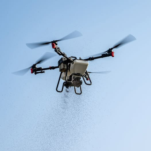
Application: agriculture / mapping mission
Requirement: long endurance under variable wind conditions
Mission behavior: long steady segments with frequent throttle corrections
Observed failures
unstable flight behavior under moderate wind (frequent throttle oscillation)
endurance drop from ~40 minutes to ~25 minutes compared to design target
one or more “unexpected power interruption” events interpreted as battery depletion
Root cause analysis (RCA)
Symptom: endurance is consistently low even when charging behavior looks normal.
What to measure: cell-level capacity check + per-cell IR mapping + minimum cell voltage under burst.
Mechanism:
capacity mismatch reduces usable energy window
IR dispersion amplifies voltage sag on throttle ramps
Root cause:
a subset of cells had higher IR and/or lower capacity
the weakest cell hit the low-voltage threshold first under dynamic load
the BMS or flight controller’s protection behavior triggered an early shutdown despite energy remaining in other cells
Engineering conclusion
System performance is defined by the weakest cell, not the average datasheet spec.
Decision-stage implication: supplier qualification must explicitly evaluate the weakest-cell behavior under dynamic load—otherwise you will re-live the same failure in the field.
C-rating vs consistency: dependency, not a trade-off
High C capability increases the penalty of inconsistency.
Why high C amplifies imbalance
When current is high:
I²R losses scale nonlinearly
a small resistance spread becomes a large sag spread
thermal differences widen faster
So a “high C” pack with weak consistency isn’t a safer pack. It can be a pack that fails more abruptly when the mission asks for transient power.
What imbalance looks like in flight logs
When imbalance exists, you typically see:
unstable voltage behavior during throttle changes
premature low-voltage warnings (even at mid SOC)
protection triggers that don’t match the remaining energy estimate
hotter-than-expected pack temperature rise for the same payload and mission time
UAV-specific implications by mission type
Mapping drones: endurance stability and predictable reserve matter more than burst.
FPV systems: transient response is critical, but IR spread still drives heat and sag.
Heavy-lift UAVs: sustained uniformity under continuous high load dominates; redundancy and protection logic become first-class design factors.
For teams designing higher-criticality architectures, Herewin’s overview of heavy-lift UAV redundancy and protection architecture can be a useful internal reference point.
A practical decision framework for UAV battery selection
This is the supplier-qualification version of “don’t get fooled by C.”
Step 1: Define the mission profile (not just the platform)
Capture a representative duty cycle:
payload range (min/nominal/max)
throttle ramp rates and transient frequency
wind and altitude envelope
operating temperature range
If you cannot define your mission as a current-vs-time profile, you are not ready to qualify a power system.
Step 2: Set electrical requirements correctly
Instead of “minimum C-rating,” define:
continuous current requirement with headroom
burst current requirement with defined duration
maximum allowed voltage sag during defined events (e.g., takeoff, gust recovery)
temperature rise rate constraints
Step 3: Evaluate cell-level consistency (not just pack-level specs)
Ask for (and verify) evidence such as:
IR (DCIR) distribution histogram across the build lot
capacity deviation mapping
cell voltage drift tracking after rest
self-discharge comparison over storage intervals
This is where supplier maturity shows up.
Step 4: Validate under dynamic load with thermal coupling
Run mission-like tests that combine:
dynamic load profiles (not constant current)
controlled ambient (hot/cold) where relevant
system-level stack (battery + ESC + motor + payload)
For general guidance on why thermal characterization matters in pack validation, NREL’s Battery Thermal Modeling and Testing overview is a solid reference. If your program experiences vibration and dynamic mechanical stress, the review article Effect of dynamic loads and vibrations on lithium-ion batteries provides a useful technical backdrop.
Engineering high-consistency battery packs
Even if you don’t control the manufacturing, you can qualify the supplier’s capability.
Benchmark table: engineering-grade vs typical variance
Below is a practical benchmark table you can use as a procurement conversation starter. Values are illustrative examples, and your final thresholds should be calibrated to mission criticality, platform class, and your own test method.
Parameter (cell-level) | Example target range | Common variance seen in the market | UAV impact if variance is high |
|---|---|---|---|
Capacity deviation | Example: ≤ 1.0% | Often 3–5% | Weakest cell hits cutoff early → reduced flight time |
Voltage alignment (delta) | Example: ≤ 5 mV | Often 15–20 mV | Higher cutoff risk during transients; balancing workload increases |
Internal resistance (IR/DCIR) variation | Example: ≤ 2.0% | Often 5–10% | Sag + localized heating → instability, faster degradation |
Self-discharge rate spread | Example: ≤ 1.0% | Varies by supplier and storage conditions | Storage drift → imbalance, higher risk of over/under-charge |
Cell grading and matching standards
A supplier should be able to show grading criteria and lot traceability for:
capacity bins
IR bins
voltage binning after formation
self-discharge screening
Thermal and environmental control during manufacturing
Consistency isn’t only sorting. It’s also process control:
humidity-sensitive electrochemical behavior
temperature drift during formation
contamination-driven dispersion
If the supplier cannot explain how they control these variables, consistency will be luck—not capability.
What to ask a supplier about consistency control
If you’re qualifying a pack for fleet deployments (not demos), use the consistency metrics above as your backbone, then ask the supplier to explain their controls across the full chain—not just their sorting bins:
Raw materials: incoming QC for cathode/anode material stability and electrolyte purity/moisture control.
Manufacturing process control: coating/stacking or winding precision, and how they reduce unit-to-unit variation.
Environment control: temperature/humidity stability and cleanliness controls that prevent contamination-driven dispersion.
Testing and screening: outgoing inspection for voltage, capacity, IR/DCIR, and self-discharge; plus stress screens (hot/cold, cycling) to remove unstable cells.
Pack build and matching: multi-parameter matching (voltage, capacity, IR/DCIR, self-discharge) with defined thresholds.
BMS balancing strategy: when passive balancing is acceptable vs when active balancing is justified, and the practical limits of balancing power.
Traceability: lot-level traceability and process records that let you root-cause a drift issue to a material lot or process step.
BMS balancing limitations
Balancing is not a magic eraser.
passive balancing wastes energy as heat
active balancing redistributes energy but has finite power and efficiency
If initial consistency is poor, the BMS spends its life compensating instead of protecting.
Evaluate your battery pack before field failure
If you’re seeing any of the following:
unstable flight performance under payload
endurance that varies across packs or batches
unexplained voltage sag during takeoff or gust recovery
…treat it as a qualification gap, not as a pilot error.
A decision-stage engineering evaluation typically includes:
cell-level IR mapping and dispersion analysis
capacity deviation analysis
thermal behavior profiling under mission-like load
system load simulation (battery + ESC + motor + payload)
Decision-stage next step
To avoid another round of field surprises, request a Battery Consistency Audit / Engineering Evaluation.
What to ask for (and what a capable supplier should be comfortable providing):
cell-level consistency report (capacity, IR/DCIR distribution, voltage drift, self-discharge)
dynamic load validation results aligned to your mission profile
thermal rise and hotspot analysis under representative transients
integration checks for ESC/motor current ramps and protection behavior
If you’re moving from lab qualification to field deployment, make consistency evidence and mission-like validation a gate—not a nice-to-have.