








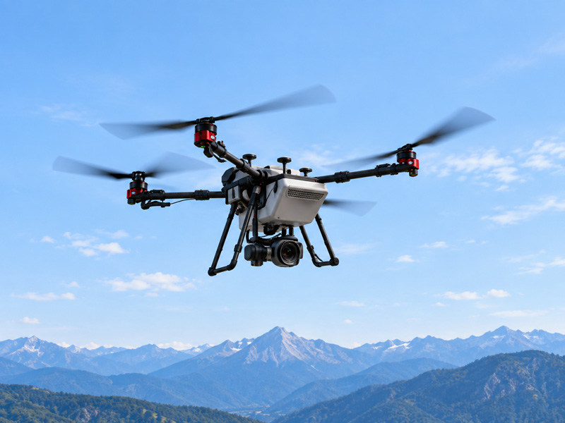



During high-temperature summer operations, commercial UAV flight crews frequently observe a puzzling pattern: an industrial drone completes its initial mission (Flight 1) flawlessly, showing stable motor currents and predictable battery discharge. The aircraft lands safely, and the crew swaps in a freshly charged battery pack.
However, within minutes of launching the follow-up mission (Flight 2) under identical payload and weather conditions, performance degrades. The flight controller issues sudden low-voltage warnings, forces active power derating, or triggers an early Return-to-Home (RTH) procedure.
Field teams routinely misdiagnose this operational anomaly as a high ambient temperature issue or a defective second battery.
In reality, the airframe enters Flight 2 in a fundamentally elevated thermal state—a condition known as thermal soak that significantly erodes usable power margin during the second sortie.
Why Flight 2 Starts From a Different Thermal State
Evaluating consecutive sortie failure requires comparing a thermally stabilized baseline launch against a pre-heated, second-sortie launch.
During Flight 1, the aircraft begins operation from a cool, baseline state. Internal cell, motor winding, and ESC temperatures are relatively close to their stabilized baseline. Because the starting baseline is low and propeller wash provides active convective cooling during flight, the propulsion system maintains ample thermal headroom to absorb operational heat without exceeding safety limits.
When the UAV lands and disarms, propeller wash stops immediately, but the heat generated during Flight 1 remains inside the airframe. Active convective cooling drops sharply, while residual thermal energy continues to redistribute across the power path, motors, and internal structures.
This continued redistribution of heat within the system is commonly referred to as thermal soak. Because individual propulsion components cool at different rates and internal thermal resistance traps heat inside, a cool external casing does not mean the system has recovered to its baseline state.
Launching Flight 2 shortly after landing creates a compounding thermal burden. Swapping in a fresh battery restores electrical energy, but field fast-charging often delivers a pack that is already warm, further compounding the airframe’s residual heat. Flight 2 combines this accumulated thermal energy with new operational heat, rapidly reducing electrical headroom and raising the risk of voltage sag, derating, and power margin collapse.
Why Surface Temperature Misleads Operators
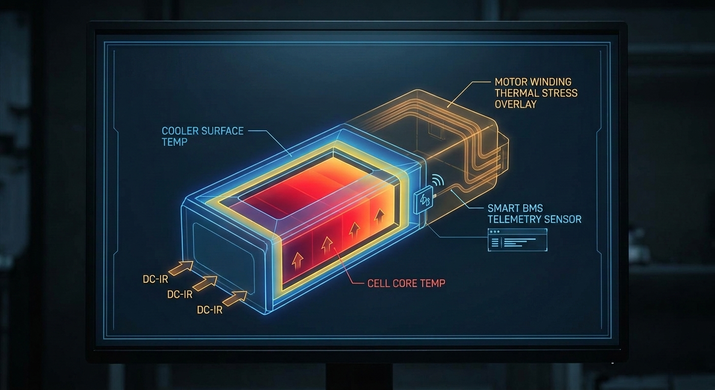
Field teams frequently overlook thermal soak because external casing temperatures cool far faster than internal cell cores, motor windings, and power electronics.
Infrared thermometers and external casing checks measure the surface, which can cool relatively quickly once the aircraft is on the ground. Internal components, however, release heat more slowly because heat must travel through packaging, structural materials, and other thermal resistance paths.
Battery: The outer casing can cool while internal cell cores remain elevated.
ESC: The heatsink temperature does not directly represent MOSFET junction temperature.
Motor: Housing temperature can lag behind internal winding temperature.
For this reason, a battery or propulsion system that feels cool externally may still have limited internal thermal headroom. Surface temperature can therefore support a relaunch decision, but should not be treated as the sole readiness criterion.
How Thermal Soak Redraws the Usable Power Margin
The operational consequence of thermal soak is best understood through usable power margin — the difference between the power the system can safely deliver and the power required to maintain the aircraft’s commanded flight condition:
P margin = P max – P req
P max is the maximum instantaneous electrical power (in Watts) the energy storage system and ESCs can supply without crossing low-voltage limits (V cut) or thermal protection thresholds.
P req is the instantaneous mechanical and electrical power (in Watts) demanded by the propulsion system to maintain altitude, lift heavy payloads, resist wind gusts, and execute flight paths.
In a cold aircraft (Flight 1), P max is relatively high while P req remains near its baseline. The resulting power margin is wide, giving the flight controller greater reserve for climb commands, payload changes, and wind disturbances.
Flight 1 — Cold Aircraft
Higher Pmax
Baseline Preq
Wide Pmargin
Stable voltage and propulsion output
Flight 2 — Thermally Soaked Aircraft
Reduced Pmax
Elevated Preq
Narrow Pmargin
Higher risk of voltage sag, derating, and early RTH
Under thermal soak (Flight 2), two simultaneous degradation mechanisms contract P margin from both ends:
Available power (Pmax) decreases: Thermal protection algorithms in the ESC derate peak allowable current, while elevated core temperatures exacerbate loaded voltage drop.
Required power (Preq) increases: Copper losses in heated motor windings (RT = R0 [1 + α(T − T0)]) degrade electrical-to-mechanical conversion efficiency. To produce identical thrust, motors must draw higher current, elevating baseline electrical demand.
The operational hazard on Flight 2 stems from this dual pressure: available power drops while required power climbs.
Thermal soak contracts the usable power margin from both sides simultaneously. P max drops due to voltage sag and thermal derating, while P req increases due to motor copper losses. The resulting margin loss deprives the flight controller of authority when responding to wind gusts or heavy payloads.
How Thermal Soak Triggers Voltage Sag and an Electro-Thermal Feedback Loop
Under high discharge loads, the interaction between accumulated heat and current demand directly drives rapid terminal voltage drop.
A simplified first-order relationship for loaded terminal voltage is:
Vterm = EOCV − (I × RDC)
EOCV is the open-circuit voltage determined primarily by battery state of charge and cell chemistry.
I is the pack discharge current demanded by the propulsion system.
RDC represents the effective DC resistance of the battery and high-current power path, including cell impedance, bus bars, connectors, and wiring.
When the battery and power path are relatively cool, effective resistance remains comparatively low. For illustration, during a high-thrust maneuver, a 150 A current demand through a hypothetical 12S pack in which each cell contributes 1.2 mΩ of effective DC resistance would produce:
ΔV = 150 A × (12 × 0.0012 Ω) = 2.16 V
The same current demand becomes more problematic if thermal soak alters the effective impedance of the battery and power path—for example, through changes in cell behavior and additional resistance in connectors, bus bars, or wiring—raising the effective resistance to 2.8 mΩ per cell (note that these calculations are illustrative rather than representative of a specific battery design):
ΔV = 150 A × (12 × 0.0028 Ω) = 5.04 V
The difference is significant. A system that maintains adequate voltage under the first condition may approach its low-voltage protection threshold under the second, particularly when the battery is already partially discharged.
For consecutive-sortie operations, the key issue is therefore not simply battery state of charge. The same current demand can produce substantially different voltage responses depending on the thermal and electrical state of the power path.
The problem can then become self-reinforcing.
When loaded voltage drops, the propulsion system may need to draw more current to maintain the required mechanical output, depending on the motor, ESC, propeller, and flight-control strategy:
Lower Vterm → Higher I → Higher I²R losses → More heat → Higher resistance → Deeper voltage sag
Heat generation in resistive elements follows:
Ploss = I² × RDC
Because resistive losses increase with the square of current, even a moderate increase in current can produce a disproportionate increase in heat generation across battery cells, connectors, bus bars, ESC power devices, and motor windings.
That additional heat can further increase electrical resistance and reduce available thermal headroom. The result is an electro-thermal feedback loop in which voltage sag, increased current demand, and heat generation reinforce one another.
This helps explain why Flight 2 can appear stable during normal cruise but deteriorate rapidly during high-thrust events such as payload climb-out, acceleration, or wind compensation. The aircraft may still have substantial stored energy, yet its instantaneous usable power margin can become insufficient to meet the demanded load without triggering voltage protection, ESC derating, or an early RTH response.
For UAV OEMs, this distinction is critical: thermal robustness is not only about keeping components below a maximum temperature. It is also about maintaining stable electrical performance as temperature, resistance, current demand, and power margin interact throughout consecutive sorties.
Why Turnaround Time Should Be Condition-Based
Faced with second-sortie power issues, field managers often implement rule-of-thumb recovery pauses, such as instructing flight crews to allow a fixed 5-to-10 minute rest between flights.
While well-intentioned, fixed-time rest intervals are unreliable because cooling depends on ambient temperature, airflow, component geometry, and internal thermal resistance—not simply elapsed time.
In elevated ambient temperatures, the thermal driving gradient between hot internal components and the surrounding air narrows, significantly slowing the rate of heat rejection. Combined with the slow outward heat transfer through internal thermal resistance layers, surface temperatures can fall while inner core temperatures remain elevated.
Consequently, relying on a fixed ground timer in high ambient heat yields inconsistent results. Ground operations should therefore move from a time-based question—“Has the aircraft rested for 10 minutes?”—to a condition-based question: “Have the battery, motors, and ESCs returned to their validated thermal operating range?”
How to Determine Relaunch Readiness
Before Flight 2, crews should evaluate available thermal and electrical telemetry against platform-validated operating baselines rather than relying on surface temperature or elapsed time alone.
Before Flight 2, Check These Signals
1. Cell Core Temperature
Use smart BMS thermistors or CAN/SMBus telemetry. Confirm the core temperature is within the platform-validated operating range.
2. Temperature Trend
Look for a stable or downward trend before arming. A flat or rising trend may indicate ongoing thermal soak.
3. ESC and Motor Temperature
Confirm temperatures remain below validated thermal derating or operating thresholds.
4. Loaded Voltage Response / Resistance Indicators
Where available, monitor loaded voltage response, pack resistance indicators, or equivalent battery health telemetry.
5. Usable Power Margin
Where telemetry allows, confirm sufficient reserve remains for takeoff, payload, wind, and maneuvering demands.
If internal core telemetry is unavailable, monitor surface temperature trends over a brief rest interval. If external casing temperature remains flat or begins rising after landing, this may indicate that internal heat is still conducting outward from the core toward structural surfaces. Surface temperature can support a relaunch decision, but it should not be the sole release criterion when internal thermal telemetry is available.
How Fleet Operators Can Manage Multi-Sortie Thermal Risk
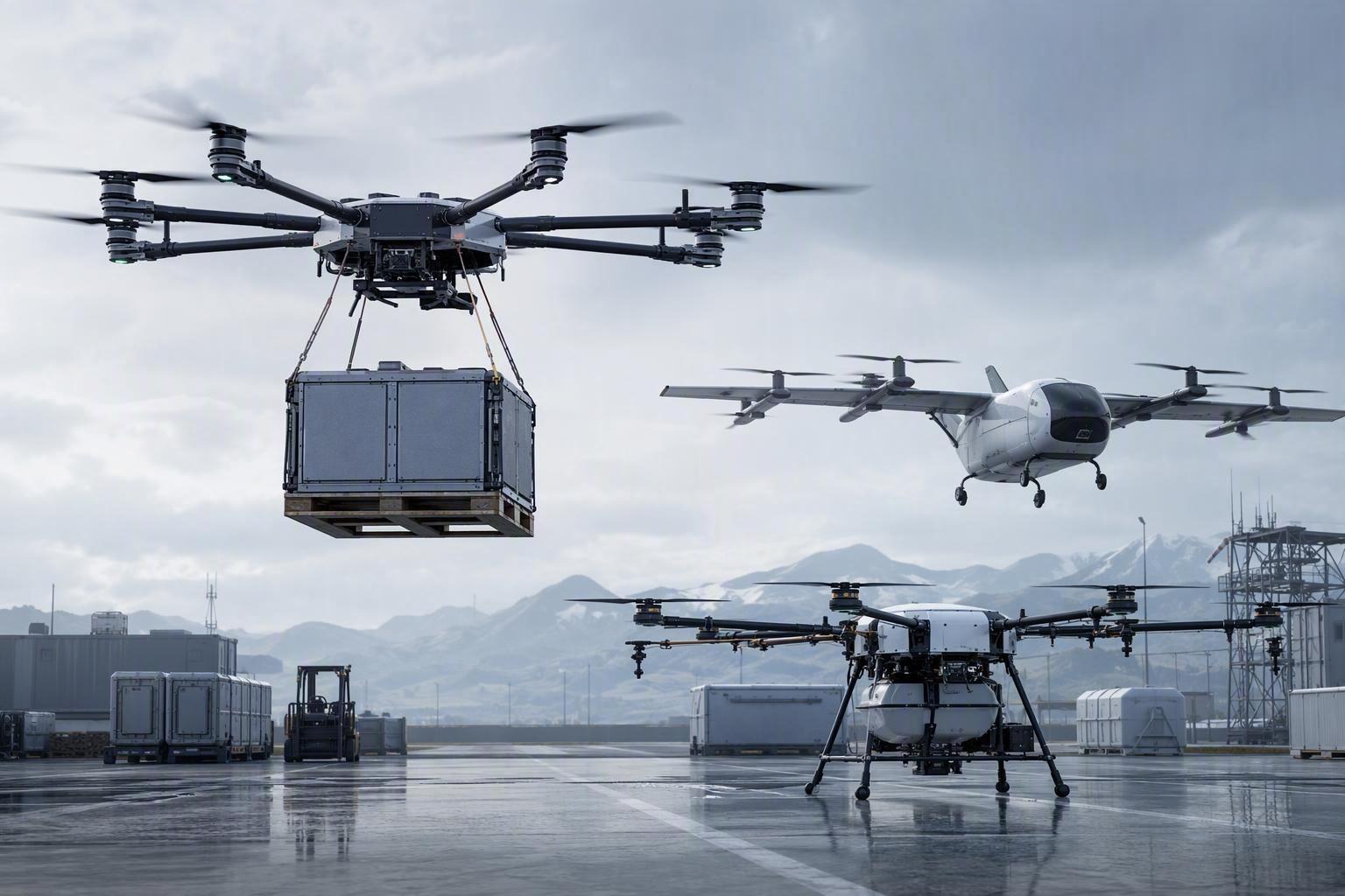
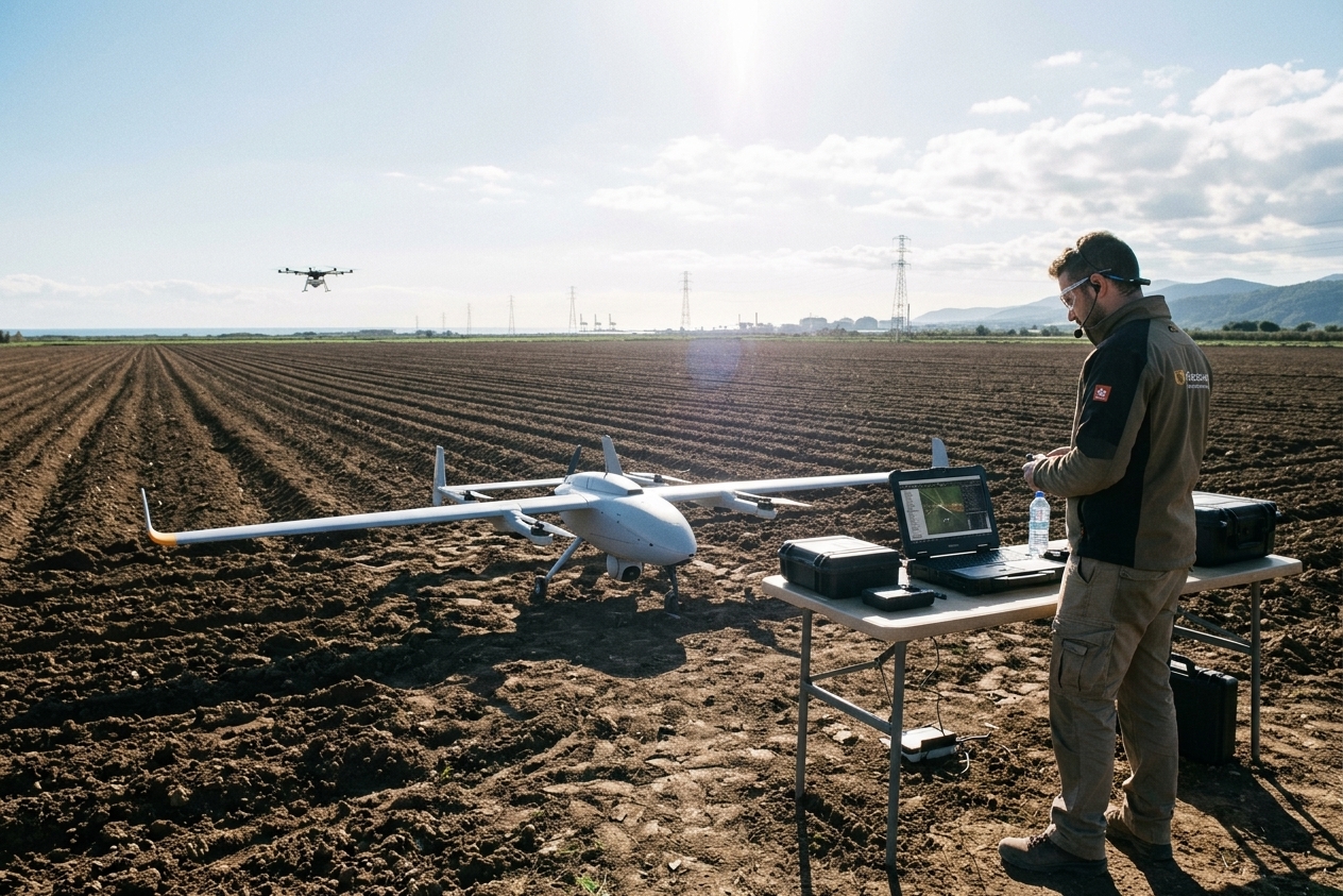
Commercial operators running high-frequency inspection, agricultural, or logistics missions must manage thermal soak without unnecessarily compromising daily operational throughput. Implementing structured field operational guidelines helps maintain safety and efficiency.
1. Rotate Battery Inventory Based on Thermal Recovery
Rotate battery packs according to their validated thermal recovery limits rather than returning the same thermally loaded pack directly into service. High-frequency operations may require sufficient pack inventory to allow thermal recovery between sorties.
2. Use Active Ground Cooling Where Appropriate
Forced-air cooling can accelerate heat rejection during turnaround, particularly in high-ambient environments, but its effectiveness should be validated for the specific battery, ESC, motor, and airframe architecture. Ground crews can review specialized industrial drone battery solutions designed with optimized cooling channels.
3. Adjust Midday Payload and Mission Profiles
When operating under peak ambient heat and solar irradiance, consider adjusting mission parameters to protect operational headroom:
Moderate climb rates to reduce peak current demand.
Reduce payload weight where operationally acceptable to expand power margin.
Schedule maximum-payload or high-altitude missions during cooler periods when possible.
These measures do not eliminate thermal limitations, but they can preserve additional power margin when ambient and system temperatures are already elevated.
What UAV OEMs Should Validate Before Deployment
Field operating practices can reduce thermal risk, but they cannot compensate for a power system that lacks sufficient thermal and electrical headroom. For UAV OEMs, multi-sortie thermal robustness should therefore be addressed during both system design and flight qualification.
Design for Thermal Robustness
OEM R&D teams should evaluate the power system across three complementary areas:
Reduce Heat Generation: Select low-impedance cell chemistries and optimize current collectors, interconnects, bus bars, connectors, and other high-current paths to minimize resistive losses under peak load.
Improve Heat Rejection: Provide effective thermal paths from cells, motors, and ESCs to the surrounding structure. Heat spreaders, conductive interfaces, ventilation paths, and other cooling features should be evaluated not only during flight, but also during the turnaround period when propeller-driven airflow disappears.
Improve Thermal Observability: Where practical, integrate battery and propulsion telemetry into the flight-control system. CAN bus, SMBus, UART, or other appropriate interfaces can provide real-time information on cell temperature, pack voltage, individual cell behavior, and battery health, allowing the system to assess thermal and electrical readiness before the next sortie.
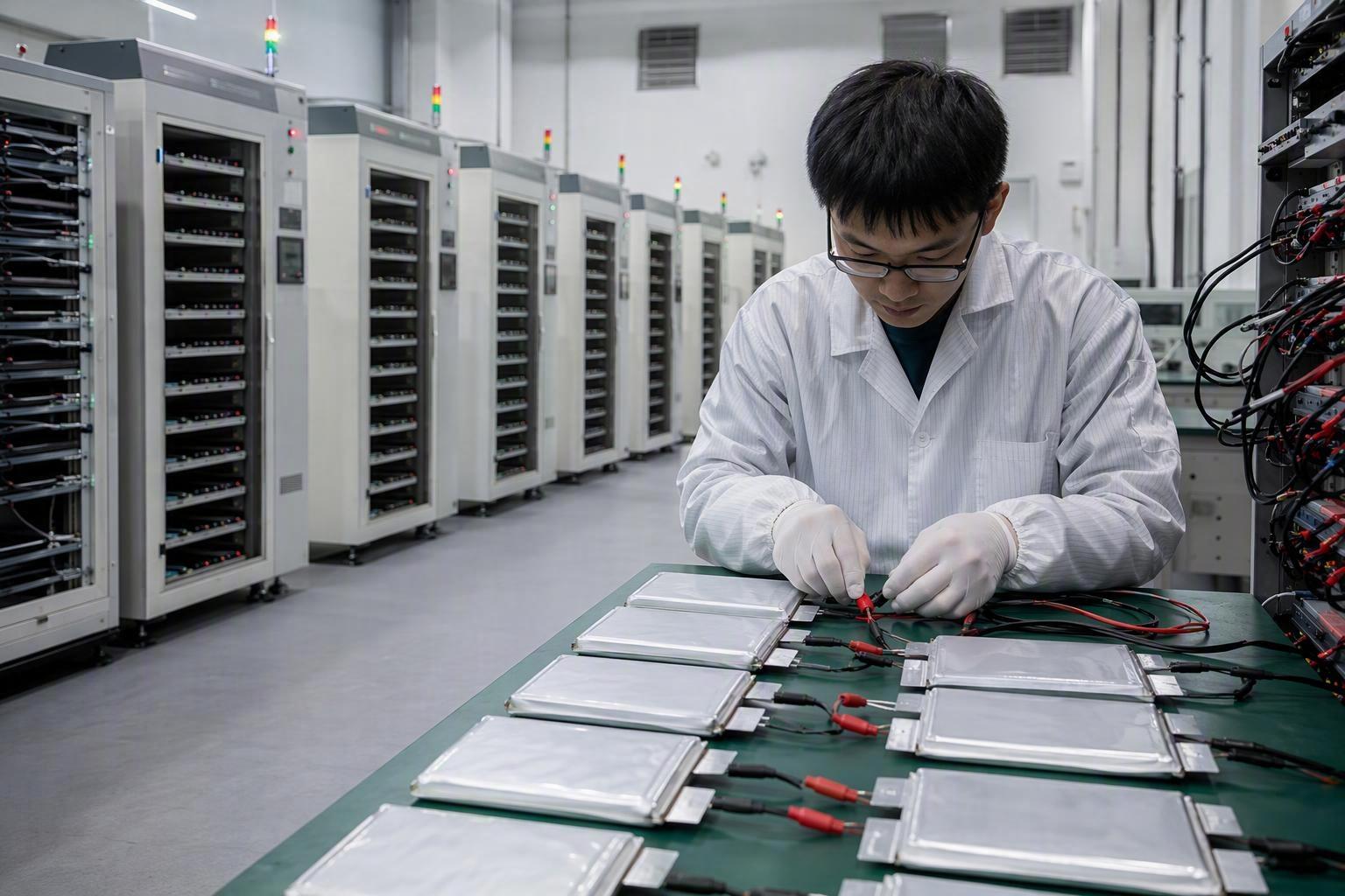
Validate Under Multi-Sortie Conditions
A UAV should not be considered thermally robust simply because it performs well during a single baseline flight. Qualification testing should deliberately reproduce the thermal states that occur during consecutive sorties:
Phase A — Baseline Flight: Test the aircraft and battery from a stabilized thermal state. Record pack voltage, voltage sag, motor current, component temperatures, and normal power consumption to establish the baseline.
Phase B — Aircraft Thermal Soak: Complete a flight, then relaunch with the airframe, motors, and ESCs still thermally loaded while using a stabilized battery. This isolates the effect of residual aircraft heat.
Phase C — Battery Thermal Soak: Repeat the test with a thermally loaded battery while the aircraft and propulsion system are returned to a stabilized state. This helps isolate battery-related voltage sag and resistance effects.
Phase D — Combined Worst Case: Test with both the aircraft and battery thermally loaded under the intended high-temperature operating conditions. This represents the most demanding consecutive-sortie scenario.
The objective is not simply to confirm that the aircraft can complete each individual flight. The critical question is whether it maintains sufficient voltage stability, thermal headroom, and usable power margin throughout the complete multi-sortie operating cycle.
A platform that passes baseline testing but shows significant degradation under combined thermal conditions may require changes to its battery, power distribution, cooling architecture, control strategy, or operational limits before deployment.
Engineering Support for High-Temperature UAV Power Systems
Multi-sortie thermal performance is ultimately a system-level problem. Battery cell impedance, pack thermal design, and BMS telemetry integration all directly affect how much usable power margin remains available for consecutive flights.
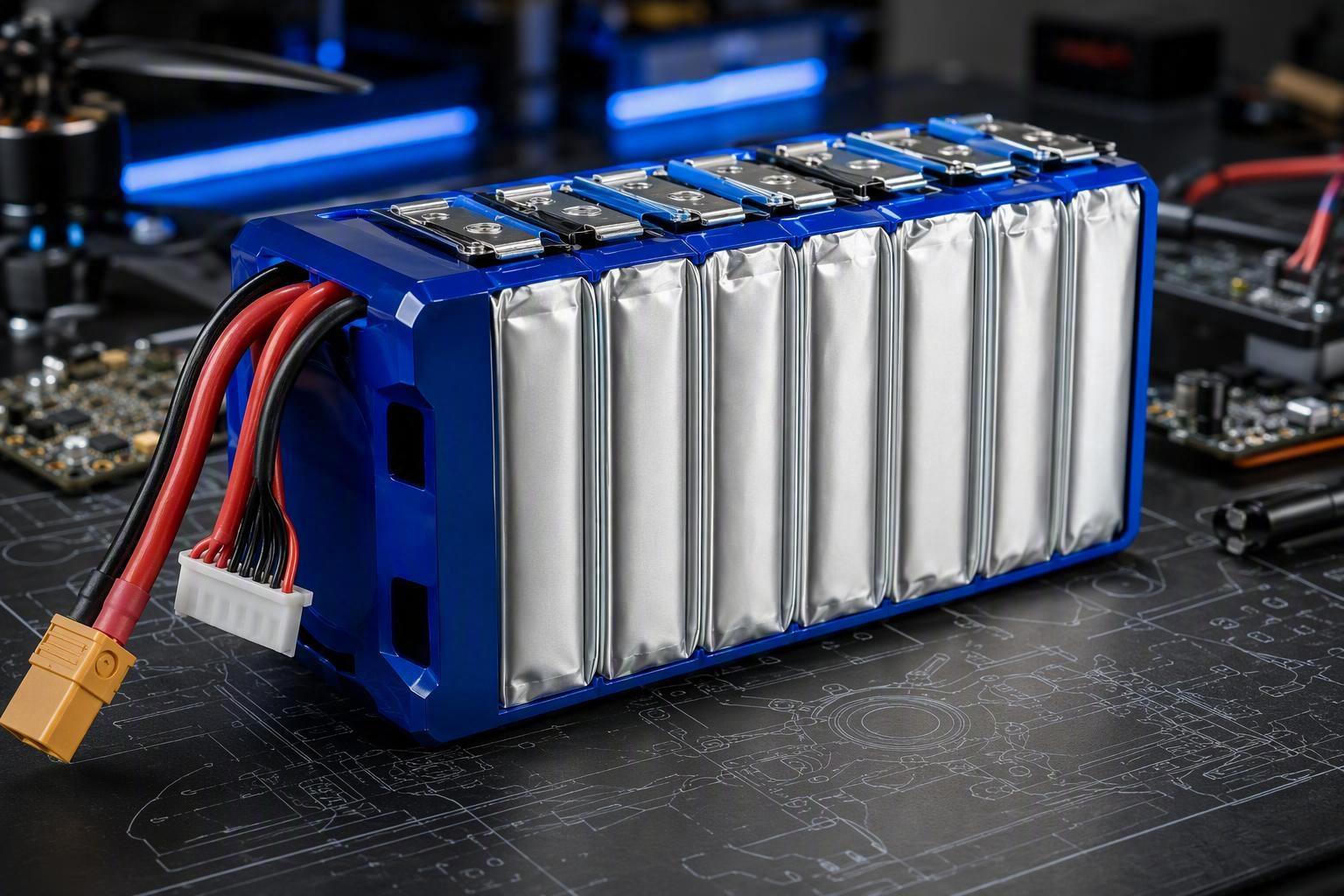
As a specialized lithium-ion polymer and semi-solid battery manufacturer with in-house cell and pack production capabilities, we develop customized UAV battery solutions around:
Low-Resistance Cell & Pack Design: High-rate LiPo and semi-solid cell configurations optimized to reduce impedance, voltage sag, and resistive losses under high-current operation.
Thermal & Telemetry Integration: Pack-level thermal design and CAN bus, SMBus, or UART communication for monitoring cell temperature, voltage, and battery health.
Application-Specific Pack Development: Custom pack configurations developed around the UAV’s load profile, available space, thermal environment, and operating requirements.
For UAV platforms operating frequent consecutive sorties in high ambient temperatures, battery selection goes far beyond nominal capacity or energy density. Cell impedance, thermal behavior, pack architecture, and telemetry capability can all affect whether sufficient power margin is maintained throughout the mission cycle.
Explore Herewin’s smart drone battery platforms or discuss a custom UAV battery requirement with our engineering team.

 Português do Brasil
  English
  Español
  한국어
한국어  Deutsch
  Français
  日本語
日本語  Русский
  Bahasa Indonesia
  ไทย
ไทย  العربية
  Italiano
  Nederlands