












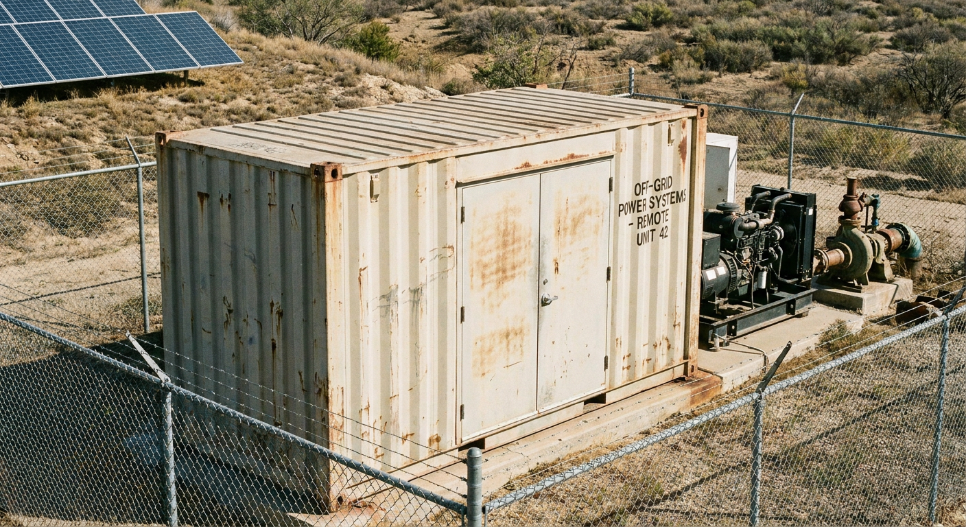
At remote industrial sites—such as agricultural pumping stations, off-grid telecom repeaters, and mining camps—site engineers operating off-grid energy storage systems (BESS) frequently encounter a perplexing failure. The monitoring dashboard indicates an off-grid battery state of charge (SOC) of 50% or higher, solar generation is active, and total energy reserves appear ample. Yet, the moment a heavy inductive load engages—whether an irrigation pump, an HVAC compressor, or an industrial air compressor—the entire system trips off instantly.
In the field, initial troubleshooting often targets the wrong components. Operators usually assume a defective lithium pack or blame the inverter board for intermittent faults. Diagnostic logs, however, tell a different story: the battery itself is fine, but the system architecture was built on a flaw—a mismatch between total energy storage and instantaneous power delivery.
An off-grid battery system doesn’t shut down during heavy startup because it runs out of power. It trips because the battery, BMS, and inverter combined can’t deliver the peak surge current without triggering a severe DC voltage sag. Nine times out of ten, the issue comes down to confusing three distinct parameters: energy capacity (kWh), continuous power (kW), and transient startup power. Fixing these shutdowns starts with looking past daily energy totals and analyzing what happens in the first few milliseconds of a high-demand event.
The Difference Between kW and kWh in Off-Grid Battery Systems
To build a resilient off-grid power architecture, energy storage engineers must separate total energy capacity (kWh) from instantaneous power capability (kW). The core relationship is modeled as:
Energy (kWh) = Power (kW) * Operating Time (hours)
Mixing up kW and kWh is the most common reason we see well-funded off-grid setups fail in the field:
kWh Defines System Autonomy (Runtime): Kilowatt-hours measure energy stored over time—the fuel tank. Sizing in kWh keeps the lights on overnight or through cloudy spells.
kW Defines Instantaneous Power Capability: Kilowatt measures active power delivery at any given second—the pipe size. kW dictates whether the system can supply enough juice to start connected loads.
Why Energy Reserves Alone Won’t Save You: Sizing a battery bank purely for autonomy without verifying discharge ratings creates a bottleneck. A high-kWh bank with a low discharge C-rate or tight BMS limits will still shut down the moment a motor starting surge hits.
This relationship is similar to electric vehicles: battery capacity (kWh) determines driving range, while motor peak power (kW) determines acceleration capability. Off-grid energy storage systems follow the exact same principle—kWh defines endurance, while kW dictates peak operational capability.
Why Motors and Compressors Cause Sudden Off-Grid Shutdowns
Inductive loads behave entirely differently from resistive loads like LED lighting or electrical heaters. Understanding the electromagnetic mechanics of motor startup explains why an apparently stable 48 V DC bus collapses under load.
Load Category | Common Equipment | Startup Surge Current / Power Impact | Primary Battery & BMS Requirement |
|---|---|---|---|
Resistive Loads | Lighting, Heaters | Minimal / No surge | Standard continuous discharge rate |
Capacitive Electronics | Servers, Telecom Units | Short inrush surge | Low DC interconnect impedance |
Inductive Motors | Irrigation Pumps, Fans | High startup current (3x–6x LRA) | High pulse discharge C-rate & low voltage sag |
Heavy Compressors | HVAC, Industrial Air | Severe transient surge (4x–7x LRA) | Configurable BMS transient delay & high peak current |
Motor Startup Surge Creates Short-Term Power Demand
At rest, a stationary AC induction motor or compressor has zero back-electromotive force (back-EMF) to resist current flow. The instant you energize it, the winding acts almost like a dead short across the circuit.
For instance, an agricultural water pump drawing 2 kW of running power might use just 10 kWh across a 5-hour watering cycle. But during motor spin-up, that same pump demands an 8 kW to 12 kW pulse for a few hundred milliseconds. While a 15 kWh battery bank easily handles the total daily energy, the BMS and inverter must be able to handle that 12 kW spike without letting the DC voltage collapse.
Motor startup isn’t a gentle ramp—it’s a millisecond-level wall of current. The battery bank and inverter have to absorb that peak without pulling the DC voltage down.
How Voltage Sag Triggers Battery and Inverter Protection
When a 300 A DC surge hits the battery bank, every milliohm of resistance across the DC circuit creates a sharp drop in terminal voltage. The magnitude of voltage sag is modeled as:
V_sag = I_surge * (R_internal + R_interconnect + R_cable)
If a 48 V LFP battery system and its associated DC distribution circuit have a combined effective resistance of 20 mΩ (0.020 Ω) and experience a 300 A transient surge, the combined DC voltage drop alone is 300 A * 0.020 ohms = 6.0 V. The bus voltage instantly drops from 51.2 V down to 45.2 V.
This voltage drop initiates a race between two protective mechanisms:
Inverter Low Voltage Disconnect (LVD): Most 48 V off-grid inverters feature a low-voltage cutoff threshold set around 42 V to 44 V. If cable losses add another 2 V of drop, the inverter senses a DC bus voltage below its threshold and shuts off immediately.
BMS Overcurrent and Undervoltage Trip: If the transient current exceeds the BMS peak overcurrent limit, or if individual cell voltages dip below 2.5 V during the surge, the BMS opens its solid-state MOSFETs. The DC bus goes dead instantaneously.
In both scenarios, the operator sees a system trip while the battery SOC indicator still shows 50% or 70% available capacity.
The Most Common Off-Grid Battery Design Mistakes
Field diagnostics across off-grid microgrids reveal recurring system design errors. Avoiding these mistakes during the engineering phase prevents costly field retrofits.
Sizing Batteries Only by kWh Capacity
Specifying an off-grid energy system purely based on daily energy consumption (e.g., “We need a 30 kWh battery bank for 24 hours of autonomy”) ignores discharge current limits. Single battery packs built with energy-dense cells may have a continuous discharge rating of only 0.5C (50 A for a 100 Ah pack). Connecting a heavy load that requires 200 A surge current causes an immediate overcurrent lockout.
Selecting Inverters Based Only on Running Power
Engineers frequently select an inverter based on the sum of nameplate running wattages. If a facility runs a 2 kW pump and 1 kW of lighting, a 5 kW inverter appears to offer ample headroom. However, if the pump requires a 12 kW startup surge for 500 milliseconds, a 5 kW inverter with weak surge capability will trip on overload before the motor reaches operating speed.
Ignoring Simultaneous Startup Loads
In automated industrial facilities, multiple inductive loads often cycle on automatically based on sensors or timers. An irrigation pump, a refrigeration compressor, and a ventilation fan may engage within milliseconds of each other. Without staggered startup delays or soft-starters, the combined surge current creates an unstoppable voltage collapse on the DC bus.
Ignoring Temperature and Battery Derating
Battery discharge capability declines significantly in cold environments due to increased electrolyte resistance. Conversely, at ambient temperatures above 45°C, smart BMS algorithms derate maximum allowable discharge current to prevent thermal damage. Sizing a system without accounting for thermal derating inevitably leads to off-grid battery system shutdown events during seasonal temperature extremes.
How to Properly Size an Off-Grid Battery System for Heavy Loads
To avoid these common field mistakes, engineers must abandon simple energy-first calculations and adopt a peak-power-first sizing methodology. Preventing startup shutdowns requires a reverse engineering approach: size for peak transient demand first, verify discharge current second, and calculate energy capacity third.
Sizing Workflow
To ensure system stability under heavy motor startup loads, follow a three-step sizing approach:
Evaluate Peak Power Demand: Calculate continuous running power and maximum surge power (accounting for Locked Rotor Amps).
Verify Battery Discharge Capability: Ensure the battery bank’s C-rate, maximum pulse discharge current, and voltage sag characteristics match inverter cutoff thresholds.
Size Energy Capacity: Determine total kWh reserves based on required autonomy hours, depth of discharge, and environmental derating factors.
Step 1: Calculate Continuous and Peak Power Requirements
Begin by listing every connected load, distinguishing between resistive and inductive equipment. Document both continuous operating power (kW) and peak surge power (kW).
Peak Surge Power (kW) = Sum of Continuous Non-Inductive Loads + (Largest Motor Running kW * Surge Multiplier)
If Variable Frequency Drives (VFDs) or soft-starters are installed, motor surge multipliers drop from 6x down to 1.5x–2.0x, substantially reducing peak inverter and battery strain.
Step 2: Match Battery Discharge Capability With Load Requirements
Once total DC surge current is established, select a battery architecture that can supply that peak current while maintaining DC bus voltage above the inverter’s cutoff threshold.
Calculate required peak DC current:
Peak DC Current (A) = Peak Surge Power (W) / (Nominal System Voltage (V) * Inverter Efficiency)
For a 12,000 W transient surge on a 48 V nominal system with 92% inverter efficiency:
Peak DC Current = 12,000 / (48 * 0.92) = 271.7 A
The battery bank must be rated for at least 275 A peak discharge current for the required surge duration. Procurement teams must inspect cell-level continuous C-rate, peak C-rate ratings, and BMS current trip specs on manufacturer datasheets rather than relying on marketing numbers.
Step 3: Size Energy Capacity for Runtime and Autonomy
Only after meeting continuous kW and peak surge current requirements should energy capacity (kWh) be finalized. Multiply average continuous load by desired hours of autonomy, then apply Depth of Discharge (DoD) and efficiency safety factors:
Required Battery Bank (kWh) = (Daily Energy Consumption (kWh) Days of Autonomy) / (Max Allowable DoD System Efficiency)
For LFP batteries, maintaining a target maximum DoD of 80% ensures long cycle life while leaving voltage headroom to prevent low-voltage trips at lower states of charge.
What Battery Specifications Matter Beyond kWh Capacity?
When procuring industrial energy storage systems for demanding off-grid applications, engineering teams must focus on five key performance parameters beyond nameplate kWh capacity:
Peak Discharge Current: Handles short-term motor starting surges without tripping.
Internal Resistance: Minimizes DC voltage sag across high-current transient events.
BMS Protection Strategy: Features transient delay curves to avoid false overcurrent cutoffs.
Thermal Management: Prevents performance derating across high ambient temperatures.
Cell Chemistry & Power Design: Ensures high C-rate capability without accelerating cell degradation.
Peak Discharge Current
Datasheets specify continuous discharge current and short-term peak discharge current (rated for 3s to 10s). For heavy motor starting, ensure the pack’s pulse discharge rating exceeds maximum calculated DC surge current with a minimum 20% engineering safety margin.
Internal Resistance
Cell and pack internal resistance directly governs voltage stability under surge load. Lower internal resistance minimizes voltage sag and reduces thermal stress during high-current events, keeping terminal voltage stable above inverter low-voltage cutoffs.
BMS Protection Strategy
A well-engineered BMS incorporates multi-tiered overcurrent protection logic. Rather than tripping instantaneously on any transient spike, industrial BMS firmware utilizes defined delay curves that allow brief motor starting surges to pass while maintaining protection against actual short circuits.
Thermal Management
Robust thermal management maintains cell temperature within optimal operational windows. Active thermal design ensures high-discharge events do not trigger automatic current derating or thermal safety limits.
Cell Chemistry and Power Capability
Cell construction dictates inherent power capability. Power-optimized LFP formulations are engineered to sustain high C-rate discharge during intense motor startup cycles while maintaining long cycle life.
How to Troubleshoot an Off-Grid Battery System That Shuts Down Under Load
If an existing off-grid installation suffers from unexpected tripping when heavy equipment starts, follow this step-by-step field diagnostic procedure to isolate the root cause.
Field Diagnostic Workflow
If an existing off-grid installation suffers from unexpected tripping when heavy equipment starts, follow this concise field diagnostic procedure:
Check DC Voltage Sag: Measure minimum terminal voltage at the inverter input during motor startup using a multimeter (min/max mode) or oscilloscope.
Analyze Fault Logs: Review inverter and BMS event logs to determine whether the shutdown was caused by inverter low-voltage disconnect, AC output overload, or BMS overcurrent trip.
Inspect DC Connections: Verify cable gauge, check terminal torque, and inspect busbars for resistive heating or loose connections.
Step 1: Check Battery Voltage Sag During Startup
Connect a Digital Multimeter (DMM) set to Min/Max voltage capture—or an oscilloscope with a DC current probe—directly across the inverter DC input terminals.
Record static open-circuit voltage at rest (e.g., 52.8 V).
Trigger the problem load (e.g., water pump startup).
Observe the minimum recorded DC voltage during the startup pulse.
If the DC terminal voltage drops below 43 V on a 48 V nominal system, the system is experiencing excessive voltage sag. If cell-level voltages remain stable but terminal voltage collapses at the inverter, the issue resides in line impedance or cable undersizing.
Step 2: Review Inverter and BMS Fault Logs
Inspect the event logs of both the inverter/charger and the smart BMS:
Inverter log shows “DC Low Voltage Shutdown”: The inverter’s protection circuit triggered first. Focus on reducing DC cable resistance, adding a soft-starter to the load, or expanding battery bank discharge capability.
Inverter log shows “AC Output Overload”: The motor surge exceeded the inverter’s peak kW rating. The inverter requires upgrading or a soft-starter must be installed.
BMS displays “Discharge Overcurrent” or “Short Circuit Protection”: The peak surge current exceeded BMS MOSFET thresholds. BMS pulse delay settings may need adjustment, or additional battery packs must be wired in parallel.
Step 3: Inspect DC Connections and Cable Resistance
High-current surges magnify tiny connection resistances. A loose lug or poorly crimped cable terminal can add resistance, resulting in several volts of additional sag during high current surges.
Use a calibrated torque wrench to verify terminal bolt torques match specifications.
Inspect DC cables for signs of localized heating, insulation discoloration, or corrosion.
Verify cable cross-sectional area and ensure low-resistance, properly sized copper conductors are kept as short as possible.
Preventive Monitoring Checklist for Off-Grid Battery Systems
To maintain long-term reliability and detect potential surge-related failures before system downtime occurs, site operators should incorporate five key parameters into routine preventive maintenance:
DC Bus Voltage Fluctuation: Monitor minimum DC voltage during heavy load engagement to identify developing cable resistance or cell degradation.
Peak Surge Current Logs: Review historical BMS current logs to ensure startup current spikes remain within safe operating margins.
Cell Voltage Balance Under Load: Verify individual cell voltage uniformity during high-discharge events to catch weak cells early.
Thermal Dissipation Trends: Track battery pack and enclosure temperatures during peak duty cycles.
Connection Terminal Torque: Inspect and re-torque high-current DC interconnects during scheduled site maintenance.
What Industrial Battery Buyers Should Ask Before Selecting a Supplier
To avoid premature system shutdowns and costly field retrofits, procurement teams and system integrators should evaluate prospective battery suppliers beyond nominal kWh and price per kWh metrics.
Key technical requirements to verify with battery manufacturers include:
Pulse Discharge Verification: Request documented peak pulse discharge ratings (current magnitude and duration in seconds) rather than relying solely on continuous C-rate specifications.
Transient BMS Tuning: Confirm whether the smart BMS firmware supports appropriate transient overcurrent handling strategies, including configurable delay parameters designed for motor starting surges.
Internal Resistance & Sag Profiles: Review DC internal resistance test reports across varying states of charge and operating temperatures.
Thermal Safety & Derating Margins: Inquire about thermal dissipation design and BMS current derating thresholds in high ambient temperature environments.
Real-Load Test Validation: Ask suppliers for empirical test data validating peak discharge capability under simulated high-surge load profiles rather than theoretical ratings alone.
An off-grid battery trip at 50% state of charge is rarely a sign of bad cells or a broken inverter. It’s the physical outcome of a system built purely around daily energy consumption (kWh) while ignoring short-term peak power (kW), motor starting spikes, and DC voltage sag.
Before signing off on equipment specifications for commercial or industrial off-grid projects, get clear answers to three questions:
What is the true peak surge current (A) and pulse duration (ms) for all connected inductive loads?
What is the total DC interconnect resistance, and will bus voltage stay above the inverter cutoff during maximum surge?
Is the BMS overcurrent protection curve tuned to ride through transient motor starting spikes without false tripping?
Building a reliable off-grid system means designing for transient peak demand alongside total battery capacity. Working with a vertically integrated manufacturer that builds its own cells, packs, and BMS firmware ensures your power architecture is built to handle real-world motor surges, not just theoretical loads.






 Nederlands
  English
  Español
  한국어
한국어  Deutsch
  Français
  日本語
日本語  Русский
  Bahasa Indonesia
  ไทย
ไทย  العربية
  Português do Brasil
  Italiano