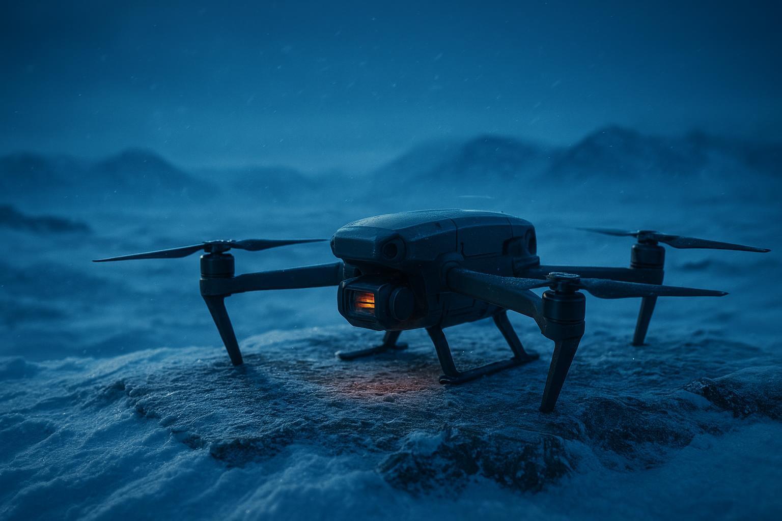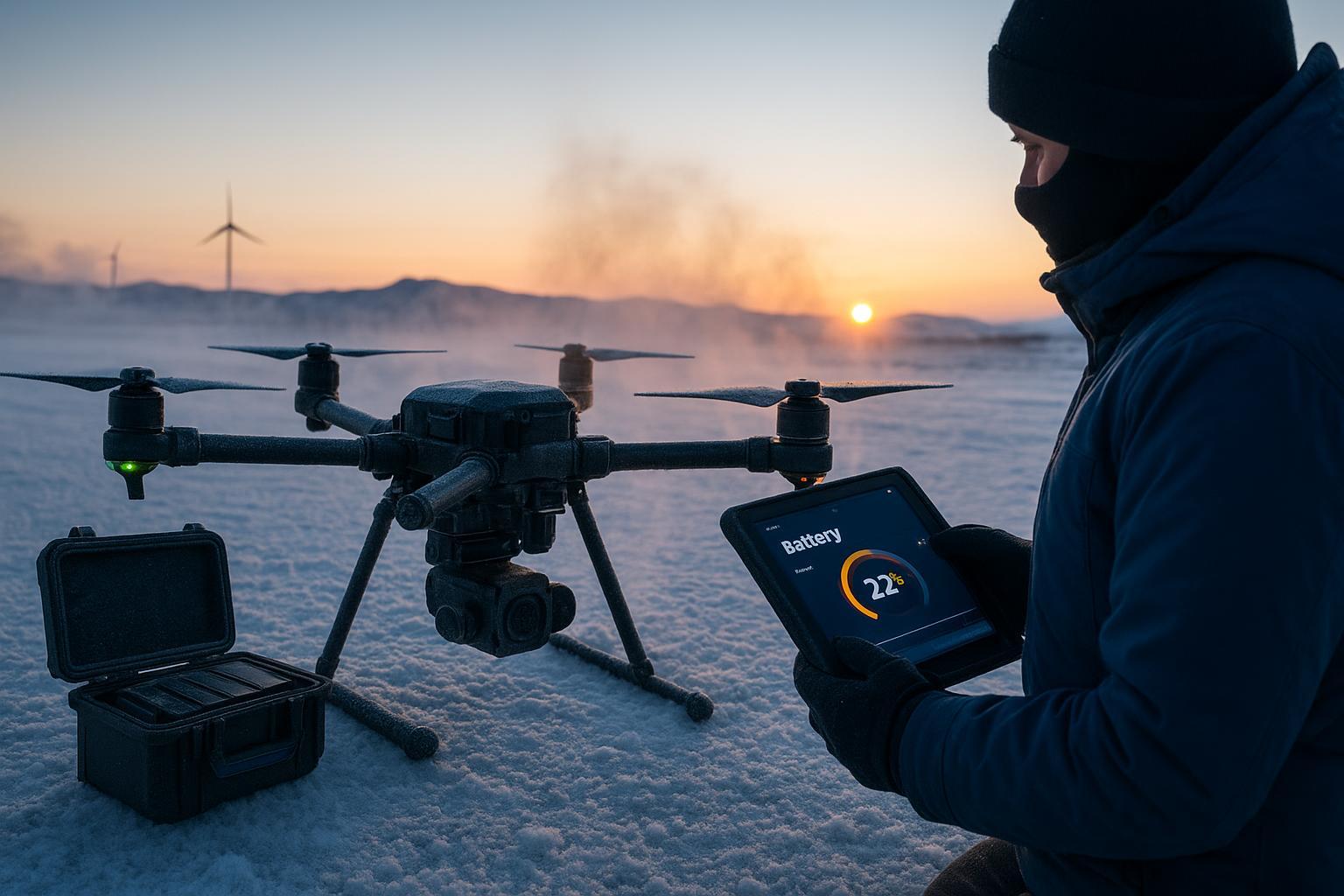


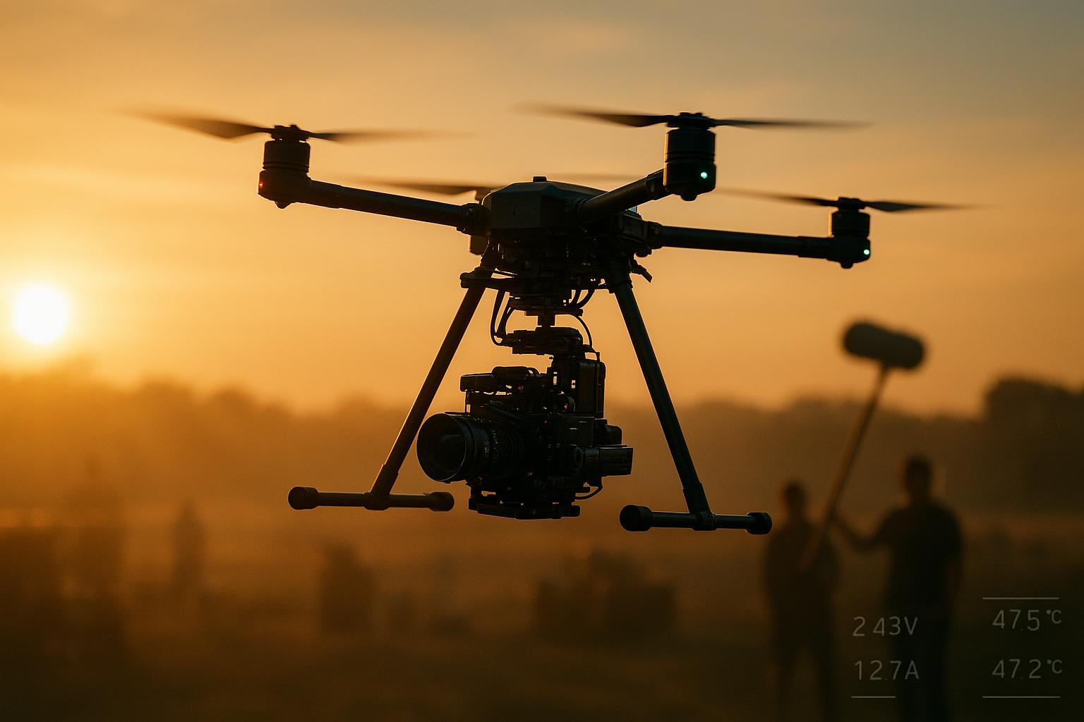
When a cinema drone carries a serious rig—ARRI or RED body, zoom glass, FIZ motors, downlink, onboard audio front end—the power system becomes the quiet hero. On long takes, small weaknesses become hard stops: a voltage dip that resets the camera, ripple that creeps into the audio floor, or a pack that hits thermal limits before the shot lands.
This guide focuses on one outcome you can measure: more follow‑shot minutes on the same rig and payload, without turning the set into a science project. We’ll walk through the production lifecycle—from power stability and on‑set noise control to turnaround, modular multi‑voltage integration, and UN38.3 logistics—using simple tests and conservative assumptions your team can reproduce.
Dynamic power stability for 8K high‑frame‑rate capture
High‑frame‑rate 8K work produces sharp load steps from camera and gimbal control, peaking current on every acceleration, focus pull, and stabilization correction. Endurance is not only about watt‑hours—it is about staying above the camera’s brownout threshold during these surges.
Suppressing voltage sag for 8K 120 fps loads
The practical way to quantify and suppress sag is DC‑IR pulse testing and wiring hygiene. A simple, reproducible protocol uses a programmable load to apply current steps at representative C‑rates, then measures the immediate ohmic drop and the slower diffusion‑related sag. Keysight’s methodology explains why short pulses reveal internal resistance and why pulse length matters; see the discussion in the article on internal resistance measurement in lithium cells from Keysight Bench Blogs 2022.
What to implement on your rig:
Keep pack‑to‑ESC leads short and fat, minimize connector count, and use low‑resistance contacts to avoid compounding the pack’s own ESR.
Validate at multiple state‑of‑charge and temperatures, then set a current ceiling that leaves margin above the camera’s input lower bound.
A note on test interpretation
Record sag at 100–200 ms after the step to capture the ohmic component and again at the end of the pulse to capture combined effects. Repeat at 25 °C and at a cold point such as −10 °C. This dual snapshot will closely predict whether a long take will survive rapid gimbal moves without tripping a camera reset.
How semi‑solid‑state and silicon–carbon anodes shift power to weight for heavy lifters
For heavy cinema rigs, chemistry choices come down to a simple question: how many watt‑hours can you lift per kilogram without losing voltage headroom during step loads.
One approach in this category is semi‑solid‑state design, which uses a hybrid electrolyte system to target higher energy density and improved safety characteristics versus traditional liquid‑electrolyte packs.
Silicon–carbon anodes may contribute to energy density, but the on‑set rule doesn’t change, a spec only matters if it holds at your coldest call time and your hardest gimbal move. The fastest way to make the decision defensible is to run the same pulse test you use for sag and compare packs under identical conditions.
Rank candidates by three field‑relevant numbers:
Wh/kg
ΔV at your peak current step
Temperature rise over a representative long take
That combination tells you whether “more energy” will actually turn into bankable minutes.
EMC on Set: Protecting Audio and Sync
Power-train noise—whether radiated or conducted—doesn’t just risk ADR; it can break timecode sync and contaminate high-gain audio preamps. While a low-ESR pack acts as a cleaner source under load steps, on-set performance is defined by how you manage the entire power ecosystem.
The “Source-Path-Loop” Framework
Source: Low-resistance pouch cells primarily reduce low-to-mid frequency ripple (Hz to kHz). High-frequency interference (MHz range) is managed by the BMS MOSFETs and DC-DC filtering. A “clean” source provides more headroom for all downstream gear.
Path: Treat your power harness like RF plumbing. Keep return paths tight, use shielded cabling, and place ferrites where cables exit the “power island” to minimize EMI radiation.
Loop: Implement a star-grounding strategy (per AES48 standards). Avoid ground loops between the camera, wireless TX, and outboard recorders to prevent induced hum and data jitter.
Why passive thermal design keeps the set quiet
Active cooling pushes heat with fans, which means noise. A pack and mount that shed heat passively—larger surface area, conductive paths to the frame, and airflow aligned with the prop wash—can hold lower cell and BMS temperatures without adding a hiss to your soundscape.
There’s also a signal-quality payoff that matters for sound: lower temperature → lower ESR → lower ripple → cleaner audio rails. Temperature isn’t the only knob, though—as SOC drops, ESR typically rises, so power quality can drift even on a stable day. It’s a subtle chain, but on long takes it helps keep the power feed consistent from slate to cut.
Expanding the operations window: energy density and turnaround
Endurance comes from two levers: increasing effective capacity at the required discharge rate and lowering the average power draw of the airframe. We focus on the first lever here—choosing cell chemistry and validating it at your mission power.
Silicon-Carbon Anodes: Performance Over Chemistry
In the field, Silicon-Carbon (Si-C) anodes are often discussed as a chemistry upgrade, but for a cinema pilot, they are experienced as a voltage-under-load curve. While Si-C increases energy density (Wh/kg), its performance is highly temperature-dependent.
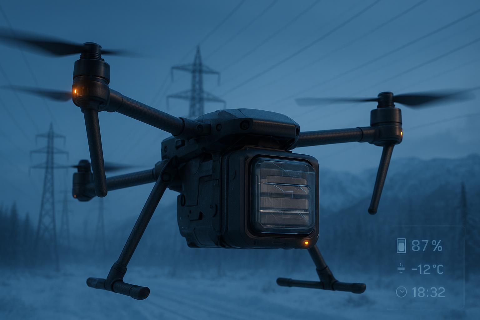
The Cold-Weather Challenge
As temperatures drop, internal resistance rises, causing deeper voltage sag during high-current events (e.g., rapid gimbal moves or heavy accelerations). This is what turns a “long-take” flight plan into an unexpected early landing.
Do not evaluate packs by nameplate capacity alone. Rank them by their Effective Capacity (Ceff) at your mission current and coldest expected call time.
Quantifying Your Margin
To move from guesswork to certainty, log two specific traces during a rehearsal:
Peak Sag: Maximum voltage drop during your most aggressive gimbal/flight move.
Recovery Rate: How quickly the voltage stabilizes after the load step.
Many professional engineering teams derate nameplate capacity by 10–30% for long-take profiles, a strategy consistent with runtime factors observed in high-density cells (e.g., Keysight 2023).
If your Ceff derate exceeds 25% due to cold-weather sag, increase your battery headroom or implement pre-heating to preserve the take.
Validation Method: Data-Driven Performance Benchmarking
Before applying the endurance estimator below, teams should lock in core parameters via a Pulse-Discharge Protocol. This process moves beyond “box specs” to reveal how a pack actually performs under cinema-scale loads.
Phase | Action | Objective |
Setup | Use a DC load with 4-wire sensing; test at 25°C and a cold point (e.g., -10°C). | Eliminate contact resistance errors and lock in the cold-weather derate curve. |
Pulse Sequence | At 100%, 50%, and 20% SOC, run 3C / 6C / 10C pulses for 3–5 seconds. | Simulate takeoff, steady flight, and aggressive gimbal/maneuvering surges. |
Data Capture | Record instantaneous sag (ΔV) at 100ms and voltage at pulse end. | Distinguish between ohmic ESR and polarization sag to set safe voltage floors. |
A neutral worked example and estimator
To translate lab data into field endurance, treat any publicly documented 6S‑class pouch pack as a reference vehicle. By applying the pulse protocol and logging P(avg) during a rehearsal with your exact camera and lens, you can compute a bankable flight time using the estimator below.
The following table uses a standard 6S 25Ah (570Wh) profile to show how environmental and operational variables shift your window. Treat this as a method, not a promise; always validate that your turnaround targets align with the cell maker’s approved charge rates and your BMS temperature gates.
Input | Conservative | Aggressive | Note |
|---|---|---|---|
Nominal energy | ~570 Wh | ~570 Wh | 22.8 V × 25 Ah |
Capacity derate C(eff) | ~80% | ~90% | set from temp + sag trace + duty cycle |
Effective energy | ~456 Wh | ~513 Wh | C(eff) × nominal |
Measured P(avg) | ~1100 W | ~900 W | pull from telemetry, not guesswork |
Estimated flight time | ~24.8 min | ~34.0 min | t ≈ Effective energy / P(avg) |
Method to reproduce:
Log P(avg) from telemetry during a representative rehearsal.
Choose a conservative C(eff) derate based on temperature and duty cycle.
Compute flight time: t ≈ Effective energy / P(avg).
The Decision Tool:
To use this as a strategic guide, set up two scenarios with the same pack:
Conservative: use your coldest-day C(eff) (often ~80%) and a higher P(avg) that includes repeated gimbal moves
Aggressive: use a warmer-day C(eff) (often ~90%) and a lower P(avg) that reflects smoother stick work
If the conservative case still clears your required shot length with a 15% safety landing reserve, you have a battery plan you can schedule a professional production around.
Fast charge as a business strategy
Fast charging is usually pitched as “faster turnaround.” On a real set, the bigger win is operational: fewer chargers, fewer spare packs staged, and less ground-time clutter.
That only works if the charge policy is honest about heat and lifetime. Safe rates depend on cell design, pack construction, and thermal control—and many high‑power pouches need conservative charge limits unless the cell maker explicitly approves higher rates and the BMS enforces temperature gates. Battery management measurement accuracy and protection logic matter here; see Analog Devices on advanced battery management and lifetime.
For film teams, cycle life isn’t an abstract lab spec—it’s depreciation and inventory planning. Using the Herewin 6S 25Ah pouch pack as a documented reference point, the specification of ≥ 650 cycles provides a baseline for calculating Total Cost of Ownership (TCO).
However, these figures assume a controlled thermal environment. If your workflow consistently pushes packs outside their optimal window through aggressive fast-charging or high P(avg) missions, you don’t just risk a missed take—you accelerate the depreciation of a high-value asset.
The practical way to size your charging lane is to work backwards:
Define Duty Cycle: Decide how many “minutes in air” you need per hour of active shooting (e.g., a 50% duty cycle means 30 mins of flight per hour).
Calculate Charge Multiplier: Determine your allowable charge rate based on cell temperature.(Example: If you fly for 25 mins and charge at 1.5C(avg), you need approximately 1.8 packs per airframe to maintain a continuous rotation.)
Audit Thermal Headroom: Don’t just measure time; measure the Δ(T) during a fast charge. If the pack hits its BMS thermal gate before reaching 90% SOC, your “fast charge” strategy will actually bottleneck your turnaround.
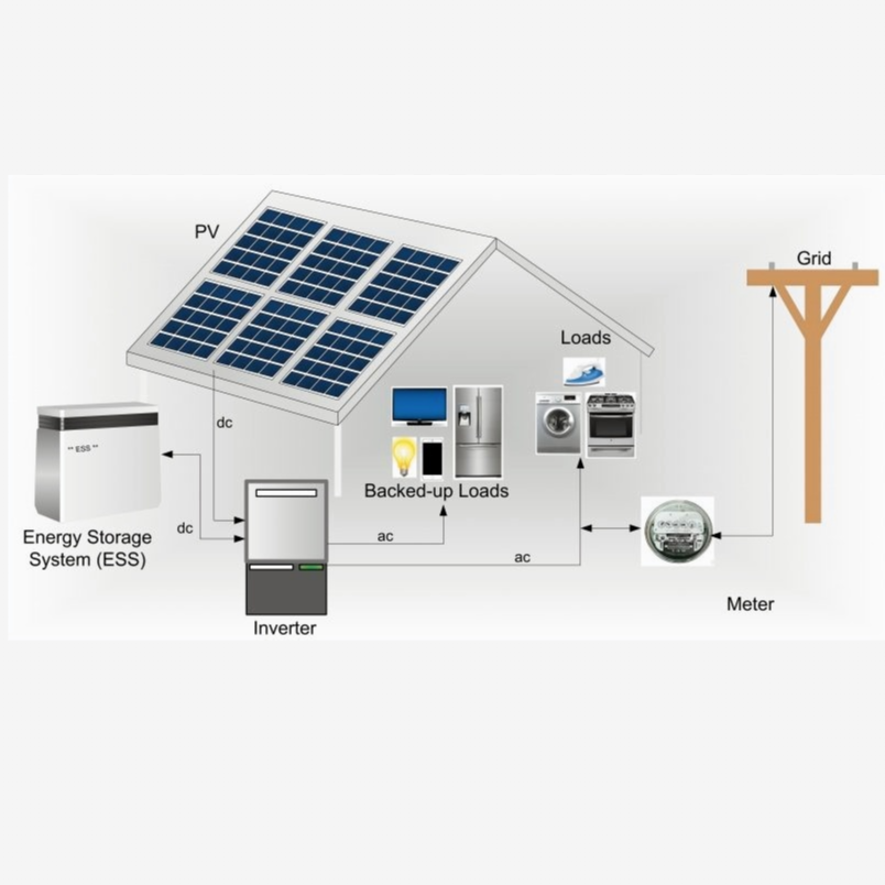
Modular customization for cinema rigs
Cinema ecosystems expect multiple voltage rails for cameras, monitors, focus systems, and accessories. Getting those rails from a single high‑S pack requires careful electrical and mechanical design.
Multi‑voltage integration for ARRI and RED 6S–18S
Know your camera input ranges and set your converter margins around them. From a battery perspective, 6S to 18S topologies are common for heavy lifters, with regulated 12V and 24V rails derived from the higher series pack.
ARRI ALEXA Mini LF: Accepts 11V to 34V DC‑IN.
RED Systems: Voltage windows vary by model; always verify DC-IN requirements in the current documentation.
The balance accuracy, current limits, and transient response of your DC‑DC stages determine whether sudden gimbal moves dim a monitor or trip a camera.
Wiring Goals: Keep high‑current paths short with minimal loop area. Route sensitive audio and video away from switching nodes.
BMS Logic: Ensure the BMS can balance all cells across the full series count while reporting per‑cell telemetry at useful granularity.
Enclosures and pack geometry: hitting the Center of Gravity
Mechanical design is power design. An enclosure that aligns the pack’s mass with the rig’s Center of Gravity (CG) reduces controller effort and lowers P(avg). It also creates more reliable airflow for passive cooling, protecting both endurance and noise floor. Use rigid mounts to prevent micro‑motion at connectors, as fretting resistance spikes are a hidden source of voltage sag under vibration.
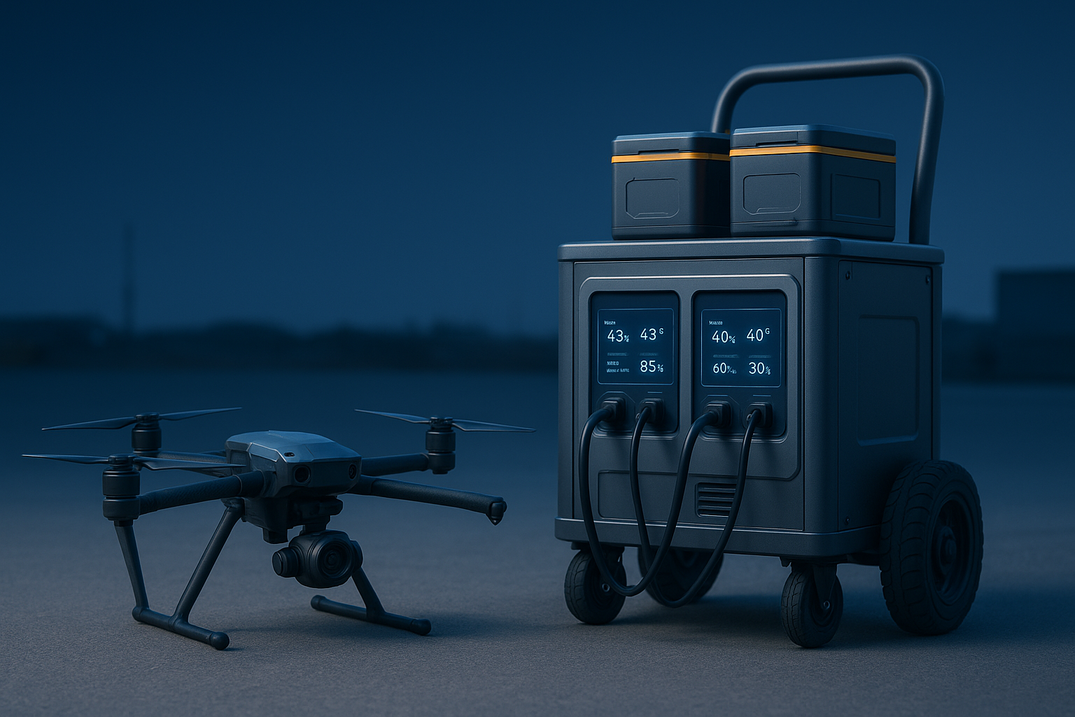
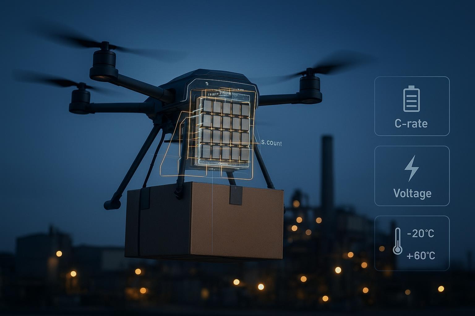
Safety at the system level: telemetry and cross‑border compliance
Telemetry turns a battery from a “black box” into a predictable asset. Logistics compliance ensures that asset moves between countries and sets without drama.
Real time BMS telemetry to prevent on set electrical risks
Log per‑cell voltages, pack current, multiple temperatures, SoC, and protection flags. During long takes or rehearsals with aggressive gimbal moves, sample at 10Hz or faster.
Protection Quality: As documented by TI and Analog Devices (e.g., TIDUF32), measurement accuracy and latency determine lifetime estimation.
Early Warning: Use this data to set alert thresholds for sag events or ΔT. A simple CSV log becomes your early‑warning system for a pack that might falter in the final minute of a long take.
UN38.3 and international shipping: Moving gear without drama
Cross‑border productions succeed when power meets paperwork. The IATA 2026 guidance emphasizes that lithium batteries shipped as cargo must meet UN38.3 tests and depart at or below 30% SoC.
Production Manager’s Checklist:
Documentation: Keep the UN38.3 Test Summary for each battery type in your documentation pack for freight forwarders.
Classification: Label correctly as UN3480 (spares) or UN3481 (packed with equipment).
Physical Safety: Protect terminals, prevent movement inside the package, and avoid shipping damaged batteries. Engage certified shippers for international cargo moves.
Three on‑set scenarios and how to apply this guide
Long take endurance
Problem: Voltage sag during hard gimbal moves can push you below the camera’s input margin and reset the take.
Solution: Validate DC‑IR at rehearsal temperatures, set a current limit that preserves margin, and track P(avg) through the entire shot. If your brownout margin is under 0.8 V at the worst pulse, reduce step intensity or increase pack headroom.
Audio‑sensitive shot
Problem: Switching noise and ground loops can contaminate preamps and break clean sync, even when flight performance looks fine.
Solution: Route power and audio with star grounding, keep cable loop areas minimal, avoid crossing audio with switching nodes, and prefer passive cooling. If you must use active cooling, test dB SPL at the boom and lav positions before roll.
Rapid turnaround day
Problem: Ground time balloons when charging lanes, spares, and paperwork aren’t sized for the day’s shot cadence.
Solution: Cap charge rates to what your cells and BMS can safely accept at temperature, size chargers to your fleet count, and pre‑stage UN38.3 documents with your shipper so replacement packs can legally move on short notice.
Data-Driven Certainty for the Long Take
You don’t have to guess your way to a long follow-shot drone battery. If you treat power like a measurable system—test it, log it, and plan with conservative assumptions—you earn something crews rarely get on long takes: certainty. The shot either clears with margin, or your data tells you exactly what to change before you roll.
If you want a second set of eyes on your test setup or your 6S–18S power architecture, consider reaching out for engineering-level support. Herewin’s team can review constraints like payload, temperature, rail requirements, and turnaround targets via the company contact form.