





A battery connector can mate cleanly and still fail to perform reliably in service. Vibration can compromise retention, contact resistance can increase voltage drop and heating, and a sealing arrangement that works in one configuration may not protect the mated assembly in another. For a UAV battery, the connector is both an electrical interface and a mechanical joint, so it must be evaluated on both counts — an early step in the wider set of UAV battery design requirements that shape a custom pack.
These problems often arise when the requirements behind the connector choice have not been defined. This guide compares common connector types, explains the four dimensions that matter in selection, and outlines the information worth sharing with a supplier before requesting a custom battery pack.
Common Battery Connector Types
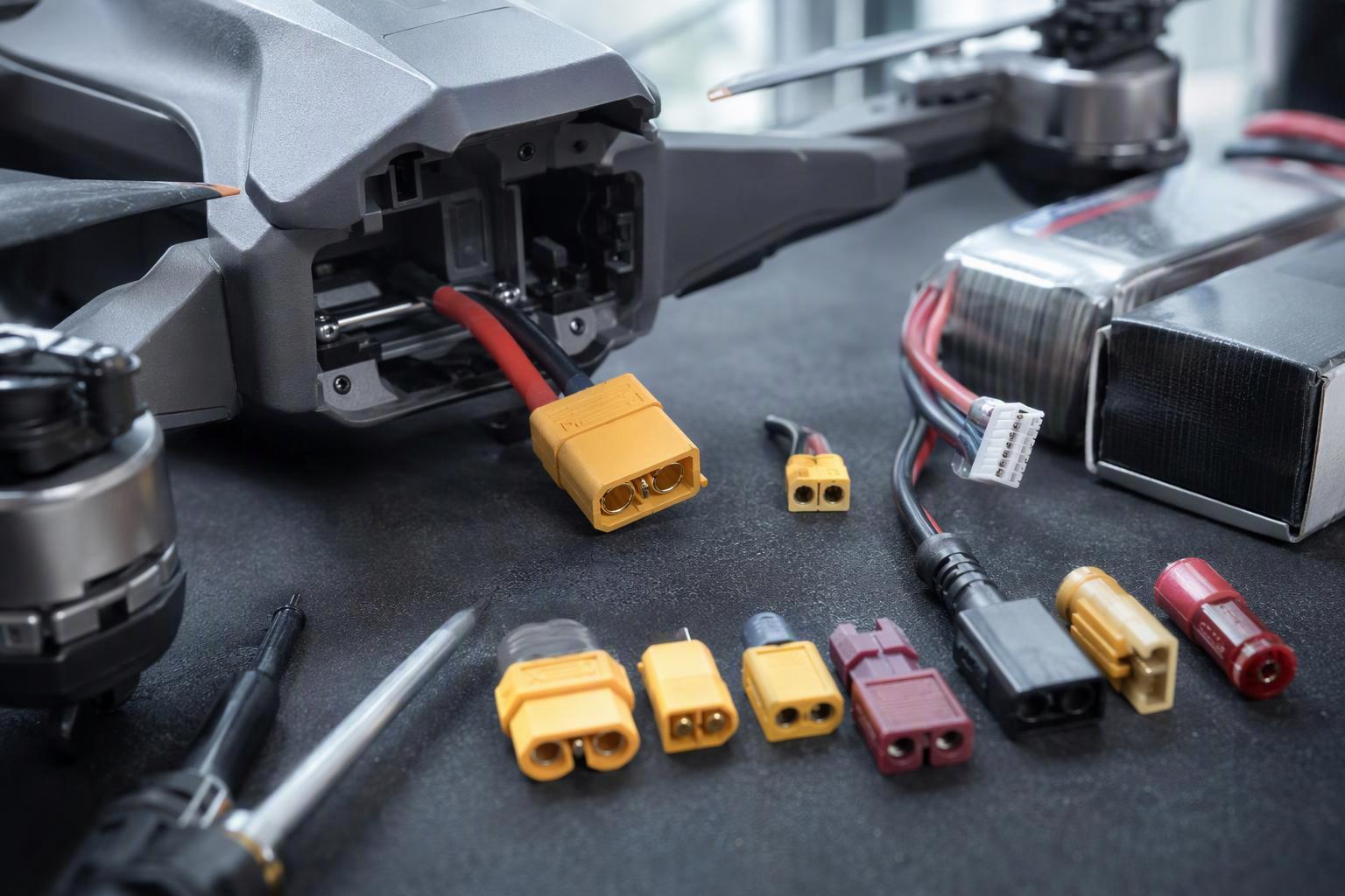
Battery connectors can be grouped by product family, interface structure and intended function. Those are three different lenses, so the groupings that follow overlap: an Anderson piece and a locking rectangular part can serve the same DC duty while sharing almost nothing structurally. The examples below illustrate common options for UAV and industrial battery systems. Real suitability comes down to the data sheet of whichever part you have in hand, which is why the rightmost column below lists what to verify rather than what to assume.
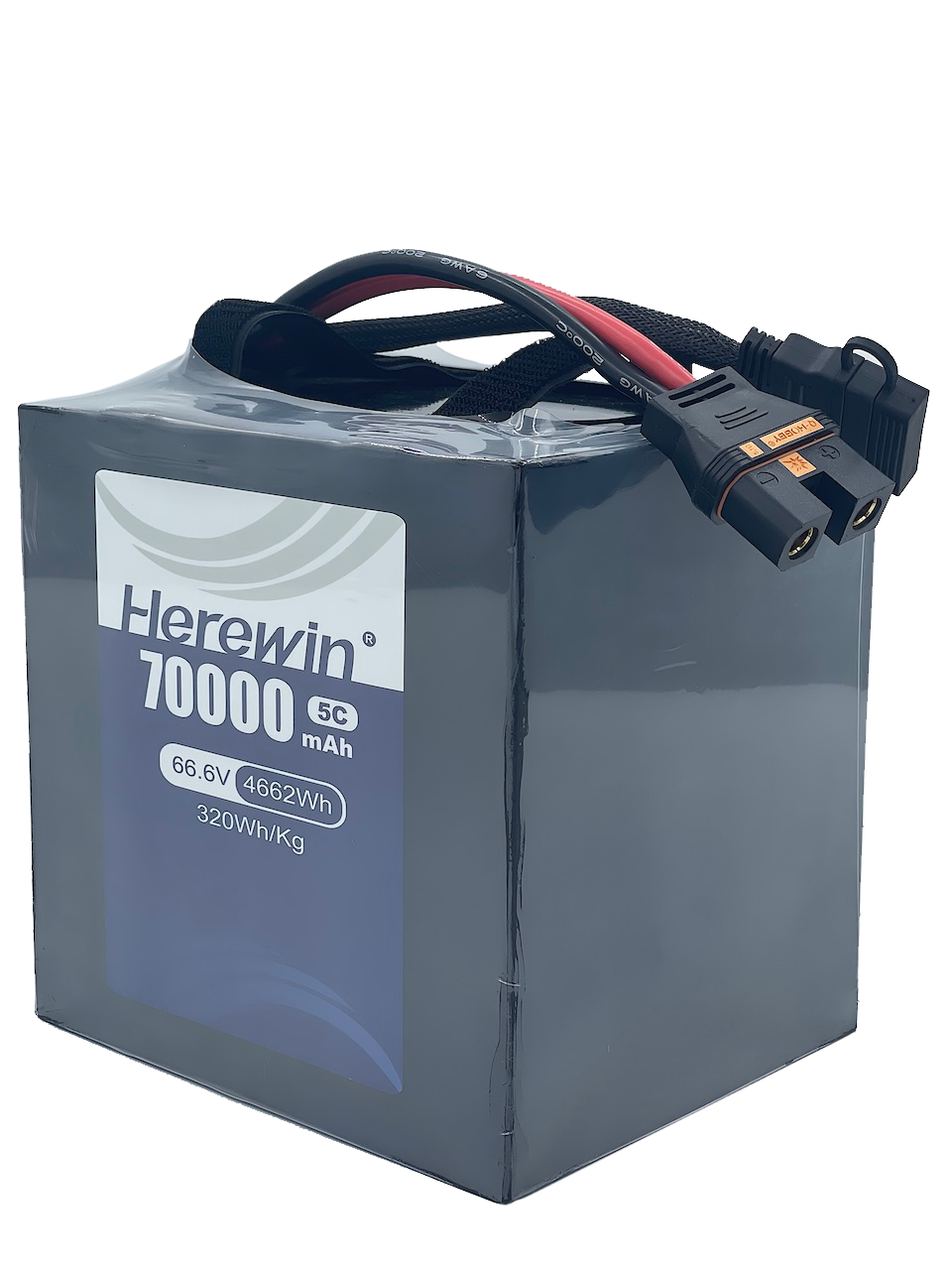
Connectors built for the same general duty can differ a great deal in contact arrangement. One common pattern uses recessed cylindrical contacts inside a molded, keyed, polarised housing, so the contacts are shielded and the housing prevents reverse mating. Another puts separate solid bullet contacts in a bulkier housing and relies on spring force to hold mating pressure. Some designs let you replace those contacts. The trade-off is that nothing shields them once the pair is apart. Anti-spark variants of either pattern add a pre-charge path ahead of the main contact. Treat these as ways of telling products apart rather than as a specification: contact form, plating, housing detail and retention all vary between models within the same line, so durability and conductivity should be judged from the datasheet of the specific part in its intended duty.
Family | Typical use | What to check on the specific model |
|---|---|---|
XT series (incl. anti-spark XT90S) | FPV, small to mid UAV packs | Rated vs momentary current, stated wire gauge, use cycles, temperature range |
EC series (EC3/EC5/EC8) | Higher-current hobby and UAV packs | Bullet diameter, housing retention, contact fit after repeated mating |
Field-swappable DC connectors | Field-swappable packs, industrial DC | Applicable electrical ratings, conductor conditions, breaking capacity and mating-cycle requirements |
Industrial locking (rectangular) | AGV, ground support, fixed installations | Sealing degree on the mated assembly, mating cycles, standard approval |
Multi-pin hybrid | Packs with signal or BMS lines | Pin count, signal pin current, keying that prevents mis-mating |
Industrial locking connectors are where endurance and sealing separate most from hobby parts, but the numbers belong to individual parts, not to the class. Rated current, ingress protection and mating-cycle life vary by model and by configuration — the insert, the hood or housing, the cable entry and the contact plating each change what a given assembly can claim. Treat any figure you see as belonging to one configuration rather than to the category, and ask for the datasheet of the exact part and housing combination you intend to use. Mixing a current rating from one size with a sealing degree from another produces a specification that doesn’t exist.
Where a pack also carries data lines, pin allocation becomes an interface question rather than a protocol question. The BMS communication protocols for smart battery data shape what signals must cross the interface, but the pin count and layout come from the protocol, the supply and ground needs, the specific signal definitions, and the connector on the device side, taken together. You can’t read a protocol name off a datasheet and count pins from it.
Anti-spark connectors add a pre-charge path to tame the inrush current that flows when a load’s input capacitors charge up. A resistor touches first and carries that initial surge, then the plug travels further and the main high-current contact closes over it, shorting the resistor out. That resistor isn’t built for operating current, and the arrangement only works as well as the specific connector and the system behind it allow.
What Matters When Selecting a Battery Connector
Battery connector selection comes down to four dimensions, and each one is a set of conditions rather than a single number. Start with what the system actually draws and how it is operated: continuous and peak current, the duration of each, the number of mate and unmate events per shift, and who performs them.
Electrical: the rating is conditional
A catalogue amp figure is only valid under the test conditions behind it. Current ratings are tied to a specified conductor size, test temperature and allowable temperature rise, so compare the full test conditions rather than the headline number.
The same part can also carry several different current ratings, because different standards and different test programmes answer different questions. A wire-to-wire rating, a rating assessed under a different regional standard, and a rating for a particular conductor size are not competing claims about the same thing. None of them is wrong, and none of them is portable to a build that ignores the conductor, the ambient and the temperature rise behind it.
Voltage drop follows the same arithmetic: it is current times loop resistance. Contact heating follows P = I²R, so the same contact resistance produces four times the heat when current doubles. The actual loss depends on the resistance under operating conditions and the current flowing through the connection. Contact losses should be evaluated separately from conductor, crimp and battery internal-resistance losses, because the same current produces different heating in each part of the loop. At high current, small resistances stop being negligible and the heat concentrates in the smallest joint. Connector selection must also match the pack’s actual load profile and maximum operating voltage, since these affect current-carrying requirements and insulation design respectively. If the pack’s continuous and peak figures have not yet been pinned down, the guidance on how a drone battery’s C-rating maps to continuous and peak current is a useful place to start.
Key Takeaway: A catalogue current rating is valid only under its stated wire gauge, temperature rise and load duration. Ask for all three before comparing parts.
Where the electrical side often stops is at the second question: how many times will this joint come apart?
Mechanical: life is counted, not assumed
Mating-cycle figures are not comparable across parts because the test basis differs. A count taken with no electrical load and with one contact plating says little about the same part under load or after plating wear, and a figure quoted for one series does not transfer to another. Where a datasheet does state a cycle life, as it often does, check insertion and extraction force, retention force, and whether the count assumes no load and a stated plating. An endurance number without those conditions attached is not a maintenance interval.
Safety: breaking capacity is a separate rating
A hot-plug rating applies only under its specified test conditions; it does not establish suitability for every live-mating or load-breaking application. The point to check on any part is whether the specification you are reading is a carrying rating or a breaking rating, because the two are assessed differently and one does not imply the other. IEC 61984 makes the split explicit: it separates connectors with breaking capacity (CBC), designed to be engaged and disengaged live or under load, from connectors without breaking capacity (COC), which are not — see the IEC 61984:2008 connectors safety standard for the scope and classification. Most published amp figures assume the part is used as a fixed connector without breaking capacity. Use the same part as a plug-and-socket device, and a lower carrying capacity may apply. Ask the manufacturer for that figure instead of inferring it from the headline number.
⚠️ Warning: If your pack may be disconnected under load, specify a connector rated for that duty rather than relying on an anti-spark feature.
Environmental: IP is a mated-state result
Picture the same connector with the cap on and with the cap off. The number printed on the box covers one of those situations, not both.
An IP rating describes the enclosure as tested, and for a connector that enclosure depends on the configuration: the cable exit, the sealing components, the mating half and any protective cap all change the result (ANSI/IEC 60529-2020 scope, 2020). For a connector, confirm which configuration the IP rating covers: the mated assembly, a capped unmated connector, or another specified arrangement. The rating should not be transferred to a different housing, cable exit or installation without supporting evidence. Temperature belongs in the same conversation, because a sealing system and a contact pair can each behave differently at the ends of the operating range; the cold-weather UAV battery testing and specification guide shows how those limits are verified in practice.
UAV and Industrial Battery Pack Requirements
UAV and industrial battery packs can place different demands on the connector interface, but the distinction depends on the equipment and duty cycle. UAV applications may prioritize low mass, compact packaging, vibration resistance and rapid pack replacement. Industrial applications may place greater emphasis on sustained-load performance, secure mounting, serviceability and installation-specific environmental protection. These are common design priorities, not fixed rules for either category.
The four dimensions don’t carry equal weight in every application either. A pack that swaps twice a day on a ground vehicle and a pack that swaps eight times a shift on a multirotor meet the same checklist but not the same priorities. The comparison below is a starting frame for weighting the requirement set, not a rulebook that separates one class of aircraft from another.
Selection dimension | UAV pack | Industrial pack |
|---|---|---|
Load profile | Continuous draw plus short, high peak bursts | Duty-cycle-dependent continuous and transient loads |
Mechanical duty | Vibration, cable retention, frequent pack swaps | Fixed mounting, mechanical hold, planned service and replacement |
Interface integration | Bay volume, device-side mating, swap ergonomics | Installation method, harness routing, equipment system interface |
Environment | Actual outdoor operating conditions | Location-specific conditions on site |
One more point applies to both columns. The interface is only part of the loop, so a high total voltage drop doesn’t tell you whether the contact pair, the harness or the pack itself is responsible. Separating those contributions takes a measurement plan designed around the actual system architecture and test conditions, not a single voltage reading at the terminals.
Wire size should be selected according to the expected continuous and peak current, cable length, allowable voltage drop, temperature rise, installation conditions and the relevant component specifications. Inspection intervals should follow the equipment and connector manufacturers’ guidance, with adjustments based on operating conditions and relevant measurements. A universal mating-cycle count or calendar interval should not be assumed to suit every application.
What to Specify When Ordering a Custom Battery Pack
Custom battery pack connector requirements are best handed over as a requirement set, not a model number. A supplier can work from the interface you already have, and a complete set removes the guessing that otherwise turns into a sample round.
Existing interface: the connector family and part number on the device side, plus a photo or drawing where one exists. If the interface is not yet fixed, the mating structure and the space available on the equipment side may also need confirming, since parts from the same family are not automatically interchangeable in a given installation.
Electrical duty: continuous current, peak current and peak duration, and pack nominal and maximum voltage.
Conductor and wiring: wire gauge for the main bus and branches, the cable type, and the run length. Whether the connector will ever be separated under load belongs here too, because a carrying rating and a breaking rating are different questions.
Mechanical requirements: expected mate and unmate events per month, who performs them, and whether the pack is field-replaceable.
Environmental requirements: the mated-state sealing degree you need, the temperature range, and any vibration or airborne qualification standard that applies.
Documentation and qualification: any test reports, datasheets or qualification evidence already on hand.
Pro Tip: Existing connector samples or equipment-side drawings can help establish the interface requirements. Electrical load and environmental conditions should be confirmed separately before a final specification is agreed.
Six items is the shape of a useful brief, not a gate. Most projects start with three or four of them filled in and the rest worked out during the discussion, so send what you have. A half-filled requirement set establishes the real constraints far better than a model number copied from an old build ever does.
How Herewin Supports Custom UAV Battery Integration
Herewin supports custom UAV battery pack development, including connector integration according to the equipment interface and project requirements. Sharing your existing connector details, electrical load profile and installation constraints helps define the requirements before a quotation or sample evaluation.
If the connector has not yet been selected, equipment-side drawings or physical samples can provide a starting point for the discussion. From there, the interface, the load duty and the environmental conditions can be agreed as part of the project scope.
Conclusion
A connector only earns its place by meeting the electrical, mechanical, safety and environmental conditions of one specific application — yours. Get those four on paper first, then share the equipment-side interface, load profile and installation constraints so the requirements can be checked against the intended duty rather than against a catalogue number.
If the interface is still being defined, start with how battery architecture choices shape a custom industrial drone pack, then bring the drawings, connector details and operating requirements into the project discussion.



 Nederlands
 English
 Español
 한국어
 Deutsch
 Français
 日本語
 Русский
 Bahasa Indonesia
 ไทย
 العربية
 Português do Brasil
 Italiano