











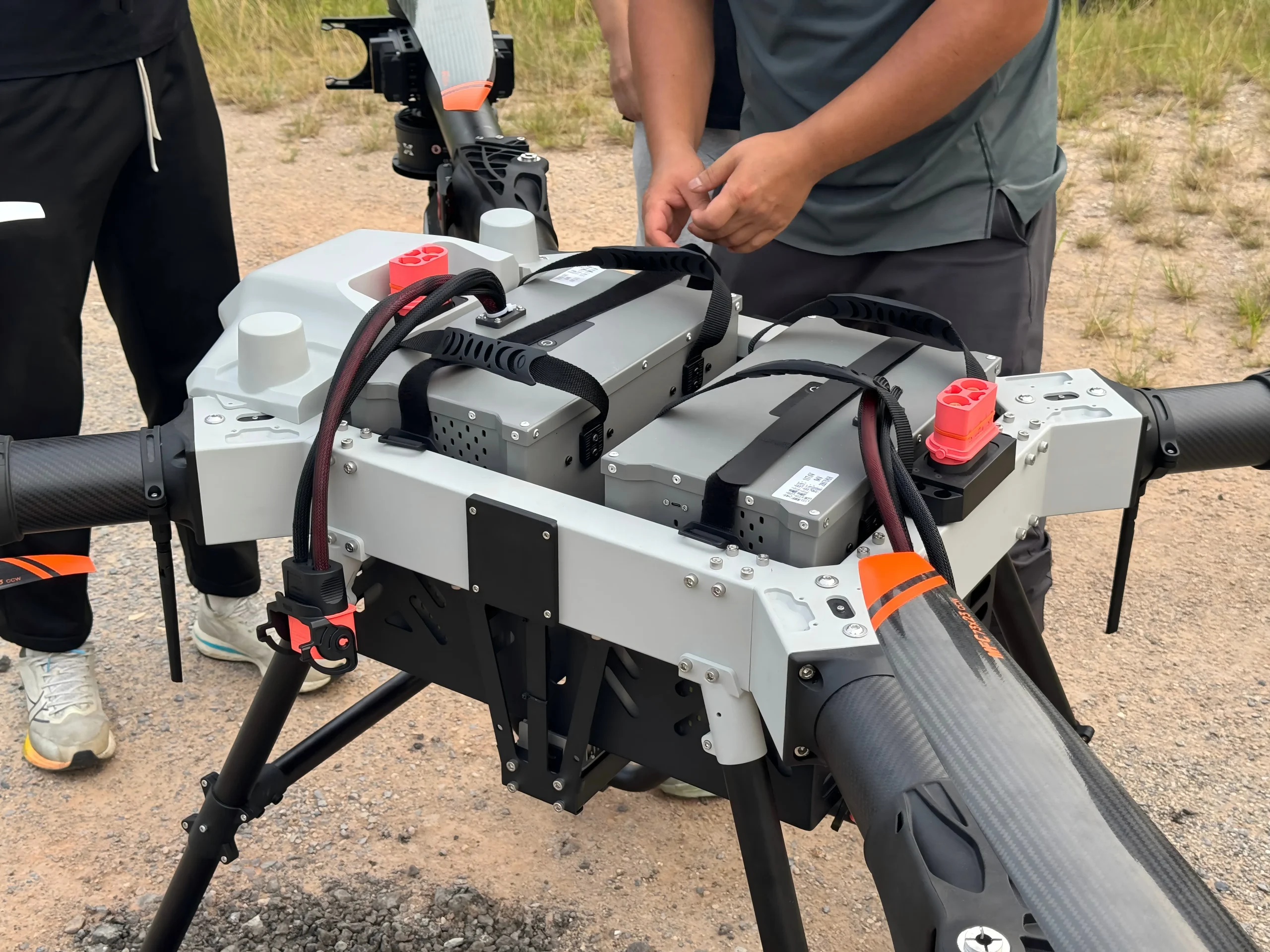
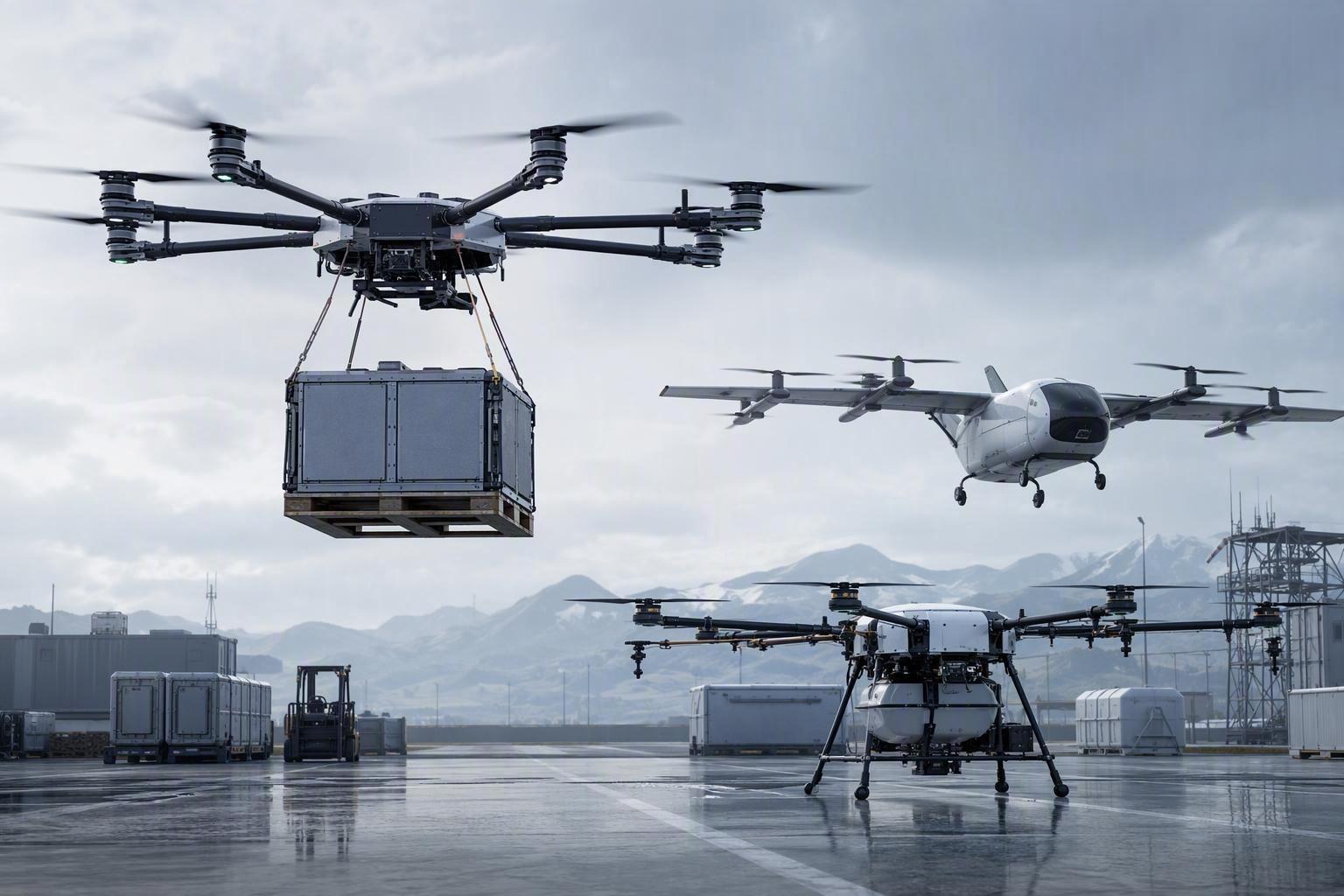
Heavy-lift UAV programs tend to hit two bottlenecks in sequence: first, whether the airframe can carry the payload; second, whether the mission can survive a single point of power failure.
In the 100–200kg class, redundancy is not simply “adding another pack.” It requires millisecond-level load sharing, backfeed prevention, and fault isolation under vibration, temperature swings, and high transient currents.
Building on our earlier MTOW Selection Benchmarks for 10–200kg UAVs, this guide focuses on the consideration stage: how to evaluate architecture choices, the risks they’re meant to control, the role of the BMS, and the evidence a supplier should be able to provide.
Why Heavy-Lift UAVs Require Redundancy System Design
The Risk of Single Battery Failure in 100kg+ UAV Missions
A single battery is a single failure domain. For heavy-lift platforms, that domain is tightly coupled to stability margins because thrust reserve is often budgeted for payload and wind, not for degraded electrical performance.
When the power source is a single pack, a small set of events can collapse mission continuity into “immediate constraint management”: sudden voltage sag under step load, an internal short, a contact resistance spike, a connector event, or a protection trip.
Redundancy design shifts the question from “will a pack fail?” to “what does the system do when a pack exhibits abnormal behavior?” That’s a question of control and isolation logic — energy density doesn’t answer it.
Operational and Qualification Requirements for Industrial UAV Power
Industrial UAV operations increasingly require:
-
Predictable return-to-home energy accounting (not just nominal capacity)
-
Diagnosable faults (so a fleet team can find root causes instead of swapping packs blindly)
-
Qualification evidence (test reports, transport documentation, traceability)
These expectations are aligned with the way other mission-critical power systems are evaluated: the architecture must maintain service under an input fault and must provide an evidence trail that explains what happened.
Physical Topologies for Redundant Power
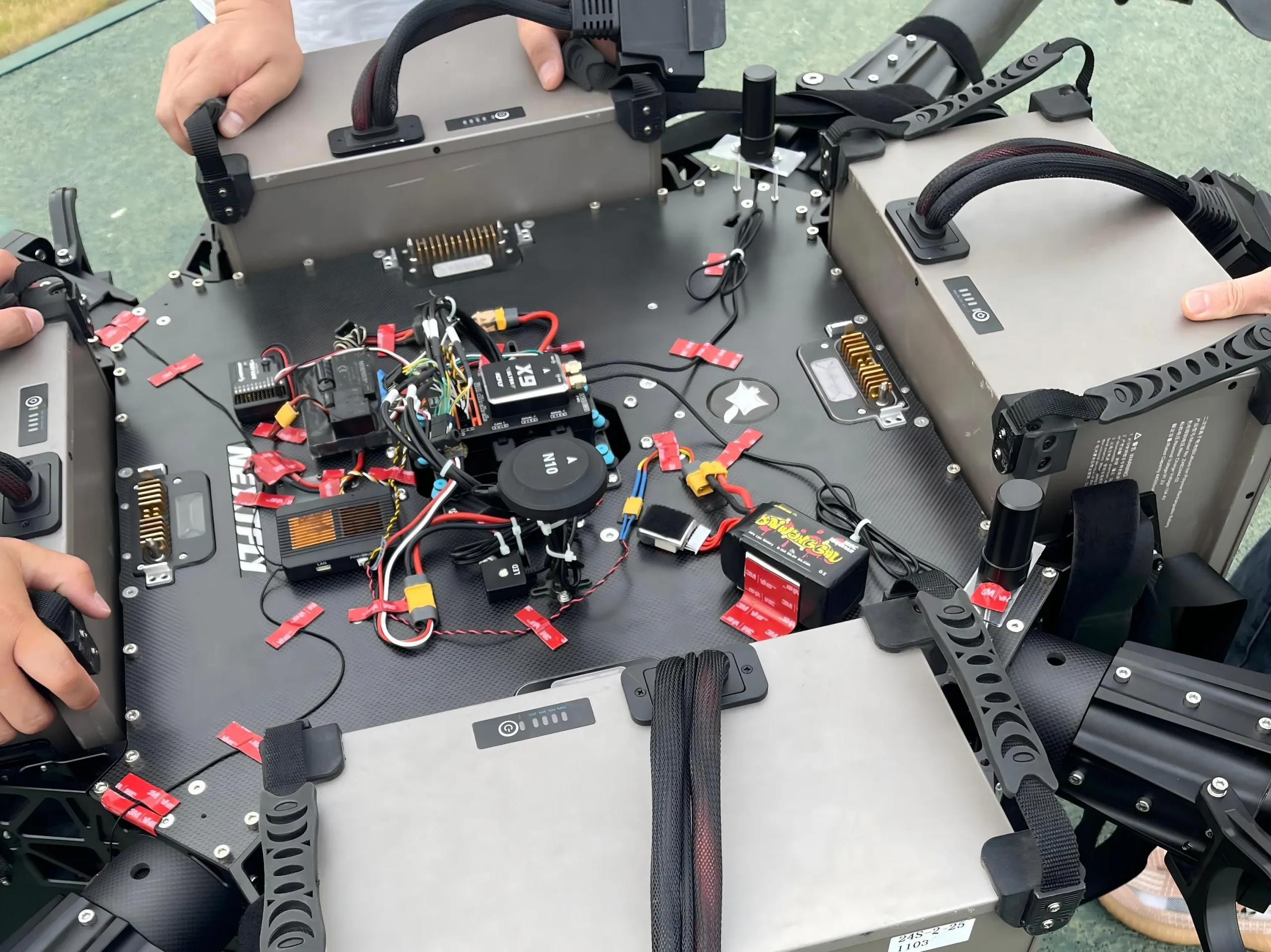
Before you compare packs, define the physical topology you’re actually buying into. In the 100–200kg class, two patterns show up most often:
-
Ideal-diode (ORing) isolated parallel: packs share a common DC bus through ideal-diode / ORing elements so they can load-share while blocking reverse current. This topology can be efficient, but it demands tight control of current sharing, fault isolation timing, and thermal management at the power-path hardware.
-
Independent power-path management (dual PMU / path-controlled): each pack feeds the propulsion power domain through its own managed path (contactors + precharge + switching control), and the system decides when to run shared, when to run single, and when to isolate. This can reduce uncontrolled circulating currents, but it raises requirements on control logic, sensing, and transition stability.
A practical decision lens is: do you need continuous load sharing, or do you need predictable isolation and handover under burst loads? The answer should be driven by measured transient currents, wiring/connector impedance, and the fault evidence you can log during flight.
In practice, ORing/isolated-parallel designs are the ones most exposed to the DCIR-mismatch and circulating-current failure modes covered later in this guide; independent dual-PMU paths trade that exposure for more control-logic complexity in the handover itself — a distinction picked back up in the efficiency section below.
Redundancy Decisions as a Heavy-Lift UAV TCO Problem
Redundancy adds mass, volume, and integration complexity, so sizing it is really a cost-allocation problem: how much of that added weight and hardware spend buys down the highest-consequence single points of failure, versus how much is just margin for margin’s sake.
A simple TCO lens weighs that added cost against three offsetting factors — the probability-weighted loss from an airframe, payload, or third-party liability event; the downtime economics of a lost mission and post-incident revalidation; and how much faster a well-instrumented fleet can isolate a root cause instead of swapping packs on suspicion. Redundancy earns its weight when it measurably moves one of these three — not simply because more redundancy sounds safer.
Thermal & Electrical Stress Under High-C Discharge
In 100–200kg platforms, redundancy design becomes most visible during burst discharge events.
If your mission profile includes aggressive step loads — such as rapid climbs, wind-gust compensation, or emergency maneuvers — the battery system may see very high short-duration current peaks (typically sub-second to a few seconds), even when the pack’s continuous discharge rating is far lower. Some mission profiles generate such peaks, but the required peak C-rate should be calculated from the actual propulsion load and pack configuration rather than treated as a fixed class-wide benchmark. The evaluation question that actually matters is whether the architecture survives these short bursts without turning small mismatches into runaway heat — continuous C-rate alone won’t tell you that.
That’s why it’s helpful to treat this section as a coupled problem: electrical stress (current sharing + reverse current + impedance mismatch) and thermal stress (localized heating + propagation risk) are inseparable at high C-rate.
If you’re doing a design review, evaluate the whole stack—pack impedance, power-path hardware, wiring/connector resistance, sensing placement, and isolation policy—because small mismatch terms can dominate both heat and aging outcomes.
DCIR Mismatch and Circulating Current in Parallel Packs
Parallel-connected cells or packs share a bus voltage, but they do not automatically share current equally.
It also matters which resistance metric you’re comparing:
-
ACIR is commonly used for production screening and cell matching.
-
DCIR is more directly relevant for system load evaluation (voltage sag, heat under real discharge, and current sharing behavior).
For redundancy, DCIR drift over temperature and aging is often what turns “matched on day one” into “imbalanced in the field.”
The core mechanism is ohmic internal resistance mismatch: the lower-resistance pack tends to carry more current, and the imbalance can widen near end-of-discharge as resistance shifts with SOC. In pack-level implementations, “circulating current” is often used as shorthand for unintended current flow between packs driven by small voltage differences (open-circuit voltage, contact resistance, wiring impedance).
Left uncorrected, that imbalance shows up first as localized heating — often concentrated at a connector or busbar, well before average pack temperature looks abnormal. That’s what makes instrumentation placement a reliability choice rather than an afterthought; efficiency loss is really the secondary concern.
SOC Imbalance and Unstable Battery Switching Behavior
Even when packs start matched, SOC estimation and drift become control problems over a fleet lifecycle. If one pack’s SOC estimator is biased, control logic that relies on SOC thresholds can cause unstable transitions — packs repeatedly entering/exiting a sharing window, or a “handover” event occurring at a moment of high load transient.
A system can look redundant in schematic form but behave noisily once estimators drift under temperature and aging. The BMS section below picks this up directly: SOC accuracy isn’t a fuel-gauge feature here, it’s what keeps pack transitions from hunting.
BMS as the Core of UAV Redundancy System Design
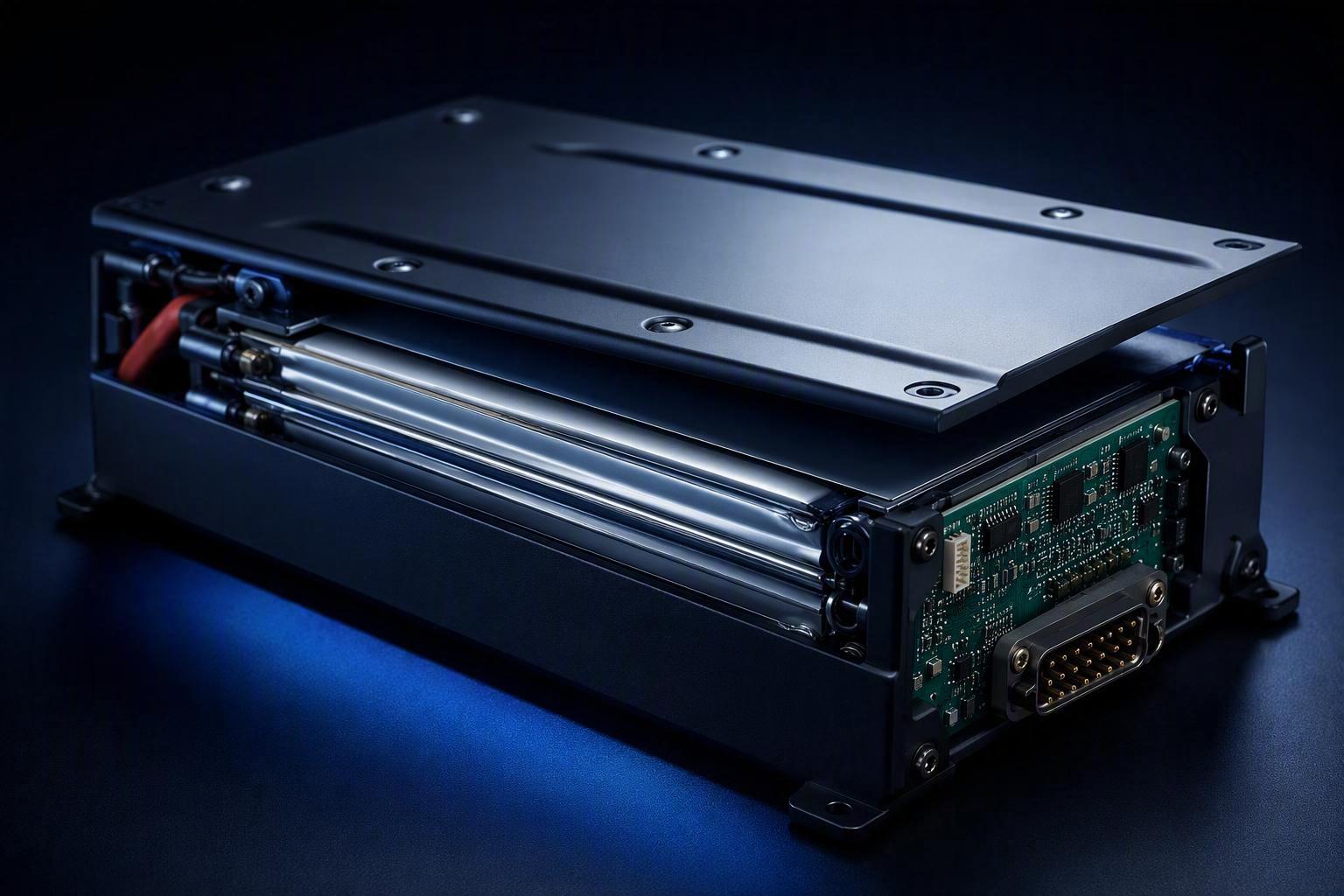
The BMS is no longer just a protection layer. In redundant architectures, it becomes a system controller: it decides which pack is allowed to source current, when to isolate, and what to log for post-flight analysis.
From Battery Protection to System-Level Control Logic
At minimum, the control layer must support:
-
Fault classification (what event occurred, how confident the detection is)
-
Isolation decisions (open a contactor, disable a path, inhibit reclose)
-
Load-sharing policy (static share, dynamic share, or hot-standby)
-
Evidence generation (CAN events, timestamps, sensor values)
This is where electrical architecture (ORing/ideal diode, contactors, precharge paths) and software policy meet.
Precision SOC as a Switching Stability Anchor
As flagged earlier, this is exactly where SOC drift turns a matched pair of packs into an unstable one: if the system policy is “handover when Pack A reaches X%,” the quality of that “X%” determines whether the transition is smooth or whether the system starts hunting — rapid, unstable switching between packs.
This is the standard our own BMS platform is measured against: combining coulomb counting with voltage compensation, our systems report SOC display errors within ±3% and support remaining-time estimation in flight. That said, any accuracy figure — including one we publish ourselves — should come with the conditions it was measured under: temperature range, C-rate, aging state. A headline percentage without that context doesn’t tell a buyer much.
This level of precision matters because mission-critical Return-to-Home logic should be driven by remaining chemical energy, not transient voltage recovery after a burst load. For architecture review, the key question is whether SOC remains stable across temperature bands, high C-rate transients, and aging and resistance growth — not just under bench conditions. If those conditions aren’t characterized, pack transitions become timing-dependent, and redundancy can behave unpredictably under stress.
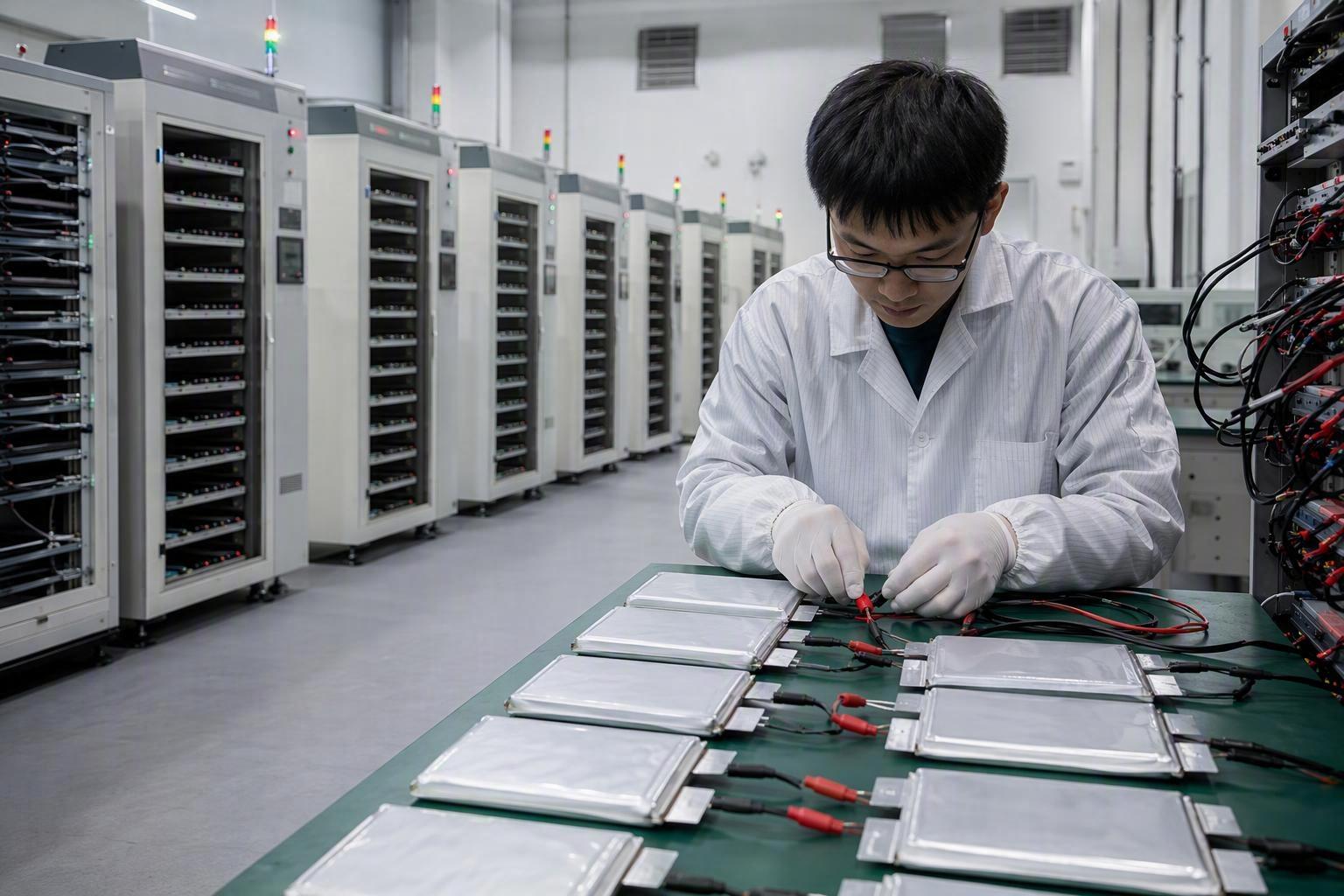
What to Request: A CAN Fault Dictionary
CAN is often the practical backbone for fault reporting, event timing, and fleet diagnostics.
A useful evaluation approach is to request (or define internally) a fault dictionary and event log spec:
-
What fault codes exist (overcurrent, cell voltage spread, overtemperature, insulation, comms loss, voltage sense lead open, NTC sensor drift/out-of-range)
-
What minimum fields are logged (timestamp, pack ID, bus V/I, contactor state, temperature channel)
-
What the isolation policy is for each class (trip once, latch-open, allow reclose after cooldown)
This is where “redundant” becomes measurable: the claim is materially stronger when fault isolation is tied to an auditable event stream rather than a black-box protection trip.
In procurement language, this is often the difference between “a BMS exists” and a defined UAV BMS fault isolation capability.
To translate these control-layer requirements into a concrete comparison tool, the following framework outlines the minimum specification fields worth requesting from any 100–200kg-class battery supplier:
|
Evaluation Item |
What to Confirm With the Supplier |
|---|---|
|
Product Model |
Is there a defined model number for batch traceability and comparison? |
|
Cell Configuration (S-Count) |
Does the voltage platform match the aircraft’s propulsion requirements? |
|
Capacity |
Is the stated value nominal or independently verified under load? |
|
Continuous / Peak Discharge Current |
Is there a test report backing this figure, and under what conditions (temperature, duration)? |
|
Redundancy Topology Support |
ORing/isolated parallel, or independent dual-PMU path management — which one, specifically? |
|
BMS Communication Protocol |
Does it support CAN (or equivalent), and is a fault code dictionary available? |
|
SOC Detection Accuracy |
What method is used (e.g., coulomb counting + voltage compensation), and under what test conditions? |
|
認証 |
Is there a certificate number or test report (e.g., UN38.3) available for this specific model — not just a company-level claim? |
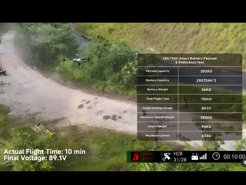
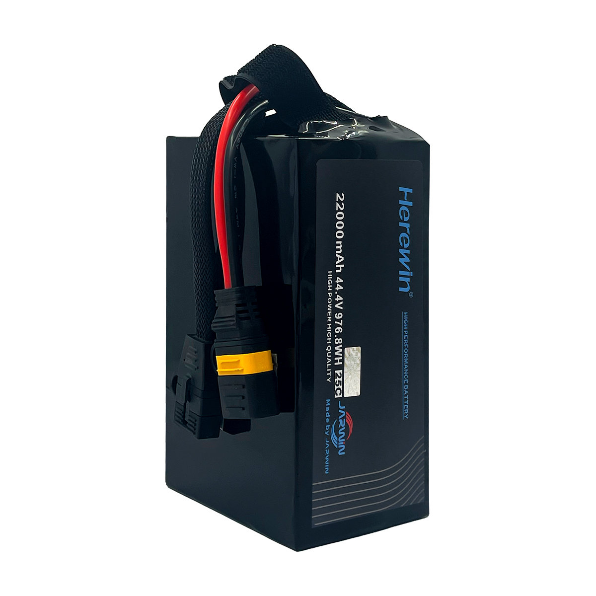
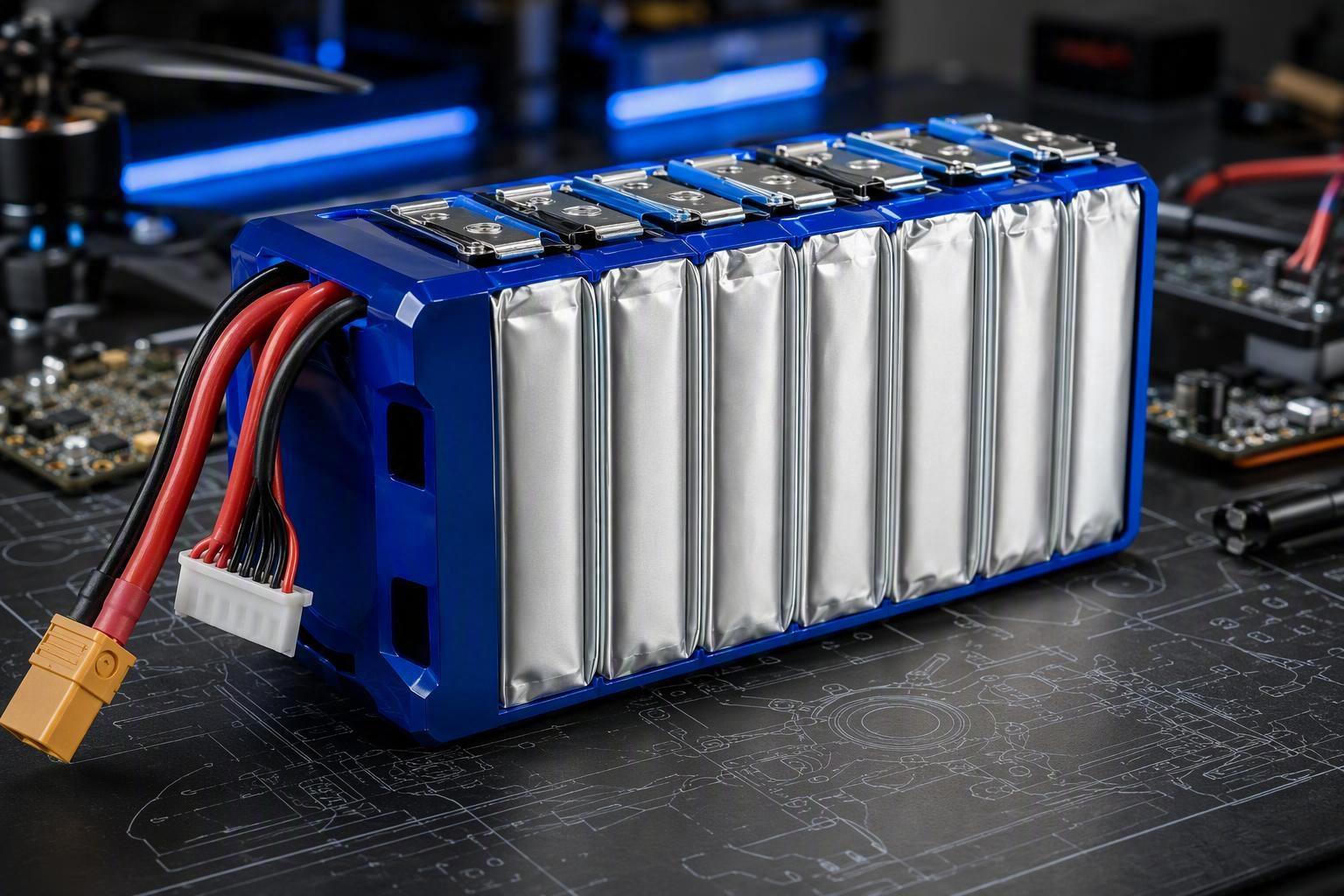
As an illustration, Herewin’s published 28S2P 103.6V 70000mAh Smart UAV Battery (model T1090190E) already discloses three of these fields: a 28S2P configuration, 70,000mAh capacity, and a 10C continuous discharge rating, measured in a full-load flight test at 202kg payload (the 10-minute figure reflects the actual flight duration for this test, not the battery’s maximum endurance).
Note that a 10C continuous rating describes sustained output, not the pack’s tolerance for the shorter high-current burst windows discussed earlier — peak/burst discharge capability is a separate spec that should be requested explicitly from any supplier, since it is not always implied by, or equal to, the continuous rating.
Thermal Safety Challenges in Redundant UAV Power Systems
Redundancy increases component count (packs, switches, connectors). That increases monitoring needs and creates more places where abnormal heat can appear.
Redundancy is also moot if control electronics fail due to environmental exposure. For industrial deployments, it’s reasonable to require at least IP65 ingress protection for relevant control hardware and enclosures, and to validate operation across a -20°C to 60°C temperature band (or your site-specific extremes).
Where Mismatch Heat Concentrates: Blocking Backfeed
The DCIR mismatch discussed above is the electrical mechanism; this is its thermal consequence, and the practical guardrail is the same one — ensure the architecture blocks reverse current and limits backfeeding paths. ORing architectures are widely used in redundant power systems specifically to prevent backfeeding and to isolate a faulty source; DigiKey’s overview describes how ORing/ideal-diode controller approaches use MOSFETs plus fast control to block reverse current while reducing the loss of diode-only solutions.
At heavy-lift power levels, this is also a hardware survivability problem. Under peak (short-duration) burst discharge, even small connector or harness resistance can create hot spots that trigger protective trips or accelerate degradation. The evaluation focus should be on where heat actually concentrates — connectors, busbars, switching MOSFETs, contactor terminals — rather than average pack temperature alone.
For UAV battery redundancy, the specific implementation differs, but the failure being avoided is similar: one source should not be allowed to sink from the bus when it is abnormal.
Thermal Runaway Risk in Multi-Pack UAV Systems
Multi-pack systems introduce propagation questions:
-
Can a fault in one pack drive abnormal current in another?
-
Can thermal energy couple through mounting structures or enclosure walls?
-
Is isolation fast enough to prevent a second pack from feeding a failing one?
Battery safety references aimed at configuration basics also highlight that parallel faults can be severe: Battery University notes that an electrical short in a parallel cell is serious because the faulty cell can drain energy from other cells, creating a fire hazard; large packs often incorporate a fuse to disconnect a failing cell in such a scenario.
Even when your architecture is pack-level rather than cell-level, the principle generalizes: a redundant source becomes a hazard if it can feed into a fault domain you can’t isolate.
Looking toward 2026–2027, semi-solid-state cells are one direction worth tracking for this class of platform: reducing the liquid electrolyte fraction is reported to suppress dendrite growth and meaningfully reduce — though not eliminate — thermal propagation risk between adjacent cells or packs. As with any safety claim in this guide, that should be verified against independent abuse-test data (nail penetration, external short, overcharge) rather than taken at face value, and evaluated on the same evidence basis as any other redundancy component: test reports, not marketing specifications.
System Efficiency and Lifecycle Optimization
Redundancy can be designed as “hot standby” (one pack active, one reserve) or as “load sharing” (both contribute). Each choice changes efficiency and stress distribution.
These two operating modes map back to the topology choice made earlier: load sharing is what ORing/isolated-parallel architectures are built for, while hot standby is the natural fit for independent dual-PMU paths, where one controller can sit idle without circulating-current risk.
Load Sharing and Battery Stress Reduction
In principle, sharing current can reduce peak stress on any single pack, but only if the sharing is controlled and stable.
The engineering concern is that poor sharing can create the opposite outcome: one pack runs hotter and ages faster, widening mismatch and making sharing worse over time.
This is why the evaluation should include measured current distribution and thermal maps, not just wiring diagrams.
Why Redundancy Can Improve Battery Cycle Life
Cycle-life improvement in high-power industrial mission profiles tends to come mainly from system-level factors: lower peak currents from better load sharing, less time spent at extreme SOC windows, and earlier detection of weak packs. With these factors in place, manufacturers in this segment commonly cite cycle-count improvements under favorable conditions — the exact result still depends on temperature, depth of discharge, and burst-load frequency, so any specific figure should be treated as conditional rather than guaranteed.
The choice of power architecture should be driven by mission intensity: a high-efficiency architecture suited to long-endurance surveying isn’t the same one that should be absorbing burst loads on a 100kg+ heavy-lift platform, and a continuous C-rating alone doesn’t describe burst tolerance — a distinction worth confirming explicitly with any supplier.
Operational Reliability in Continuous Industrial UAV Missions
For continuous operations, redundancy also becomes an operations feature:
-
Predictable pack retirement rules (based on logged events and impedance growth)
-
Swap policies informed by actual duty cycle, not calendar time
-
Reduced “mystery faults” because events are traceable
Why Redundancy Is Becoming Industry Standard in 100kg+ UAVs
Redundancy adoption isn’t driven by abstract safety arguments alone; it’s being pulled by measurable changes in mission consequence, utilization, and evidence expectations.
Cost, Downtime, and Qualification Pressure
Three converging pressures make “unknown electrical faults” prohibitively expensive in heavy-lift programs:
-
Higher mission consequence: higher payload value and third-party liability exposure
-
Higher utilization: shifting from hobbyist cycles to rigorous industrial duty cycles
-
Higher evidence expectations: the need for professional qualification artifacts and transport compliance
UN 38.3: More Than a Shipping Checkbox
UN 38.3 is the mandatory baseline for lithium battery shipping, but its value in heavy-lift programs extends beyond legal compliance. Two of its test categories are double as practical reliability proxies: vibration testing validates the physical integrity of sense-wire harnesses, connector seating, and fastener/torque stability over long-term operations, while external short-circuit testing benchmarks the millisecond-level isolation response of the BMS under severe electrical stress. For industrial buyers, these are often part of the minimum evidence bar used to qualify hardware robustness.
Beyond shipping compliance, this same evidence mindset applies to day-to-day fleet operations: clear isolation events (what opened, when, and why), synchronized current/temperature telemetry around transitions, and confident fault classification are what let a fleet team diagnose a power system instead of doing “swap and hope” maintenance. Ultimately, a redundant architecture helps ensure that when a fault occurs, the system remains a controlled, auditable asset rather than an untraceable liability.
Next Steps: The Evidence Package
Architecture choice, the risks it’s meant to control, and the BMS logic that enforces it are only as credible as the evidence behind them. If you’re comparing approaches for a 100–200kg class platform, a practical next step is to request (or define) a single “evidence package” that makes architectures comparable:
-
Electrical architecture diagram showing isolation elements (contactor/ideal-diode/ORing concept) and backfeed prevention paths
-
BMS fault dictionary + isolation policy (what trips, what latches, what recloses)
-
CAN event/log spec (fields, timing, retention)
-
Current-sharing and thermal test results under representative duty cycles
-
Transport and compliance documentation scope (e.g., UN 38.3 test summary/report availability)
To access detailed technical documentation on industrial power reliability, BMS monitoring protocols, and multi-pack configuration benchmarks, we welcome you to consult the Herewin technical team. Our engineering experts can provide the necessary baseline references and integration guidance tailored to your specific heavy-lift UAV program.

 日本語
日本語  English
  Español
  한국어
한국어  Deutsch
  Français
  Русский
  Bahasa Indonesia
  ไทย
ไทย  العربية
  Português do Brasil
  Italiano
  Nederlands