










Industrial UAV OEMs rarely miss their mission targets because they chose the wrong cell chemistry. They miss because the aircraft can’t close the loop on real constraints: center of gravity (CG), usable internal volume, harness routing, thermal headroom, vibration loads, swap workflow, and production repeatability.
As industrial UAV platforms move from standardized survey drones toward specialized systems for inspection, delivery, agriculture, and defense applications, battery architecture has become harder to separate from aircraft architecture.
That’s why battery selection for customized platforms has changed.
Old mental model: battery selection = energy density and voltage.
Industrial UAV reality: battery selection = UAV battery pack architecture, and architecture directly shapes platform integration.
This is not a soft-pack sales pitch. It’s a consideration-stage decision guide for OEM R&D and power-system leads who need to make faster, cleaner platform decisions—without discovering late in EVT/DVT that the pack can’t fit, can’t cool, or can’t hold CG.
Why battery architecture has become an aircraft design decision
Consumer drones can often treat the battery as an interchangeable accessory. Industrial platforms can’t.
Custom industrial drones are mission-built around:
inspection / mapping payloads (gimbals, EMI constraints, specific mounting rails)
delivery payload bays (turnaround time and swap access are design parameters)
agriculture / emergency response duty cycles (heat soak, dust, vibration, high daily cycles)
fixed-wing VTOL layouts where fuselage volume is already allocated to structure and avionics
In these airframes, the battery isn’t just an electrical module. It’s often the dominant packaged mass and one of the largest contiguous volumes. If the pack geometry forces airframe compromise, “better cells” rarely save the program.
A useful parallel from electrified aircraft programs is that you never fly cell-level numbers—you fly the system after structural, thermal, and safety overhead is added. NASA discusses these pack-level penalties in Battery Cell-to-Pack Scaling Trends for Electric Aircraft (NASA, 2021).
In customized industrial drones, form factor selection is a platform decision—not a component decision.
Why standard battery formats create integration constraints
Standard formats aren’t “wrong.” But they can force design compromises when the airframe is geometry- and workflow-constrained.
Where cylindrical cells work well
Cylindrical cells remain attractive because of maturity, supply chain availability, and mechanical robustness.
Where cylindrical formats limit custom UAV designs
At pack level, cylindrical defaults create three predictable penalties in constrained aircraft:
Geometry penalty: more dead space, more structure, and fewer “good” pack placement options.
Interconnect penalty: more welded/bolted interfaces to design, qualify, and keep stable over life.
Integration penalty: you place the pack where it fits—not where it best supports CG, harness routing, cooling, and swapping.
How soft pack architecture helps custom UAV platforms
Pack shape matters because it determines where mass and heat can go inside a constrained aircraft.
For customized platforms, the coupling is system-level:
CG ↔ controllability: payload changes already shift CG; battery placement sets the baseline margin.
structure ↔ payload: enclosure and mounting mass are paid for with payload.
thermal path ↔ power stability: high C-rate bursts are a thermal problem before they’re a chemistry problem.
swap workflow ↔ uptime: bay access and connector placement determine field error rates.
So the practical question isn’t “which cell has higher Wh/kg?” It’s: which architecture lets the airframe stay clean while meeting mission constraints?
“Soft pack” (pouch) is often dismissed as fragile consumer hardware. That’s a category mistake.
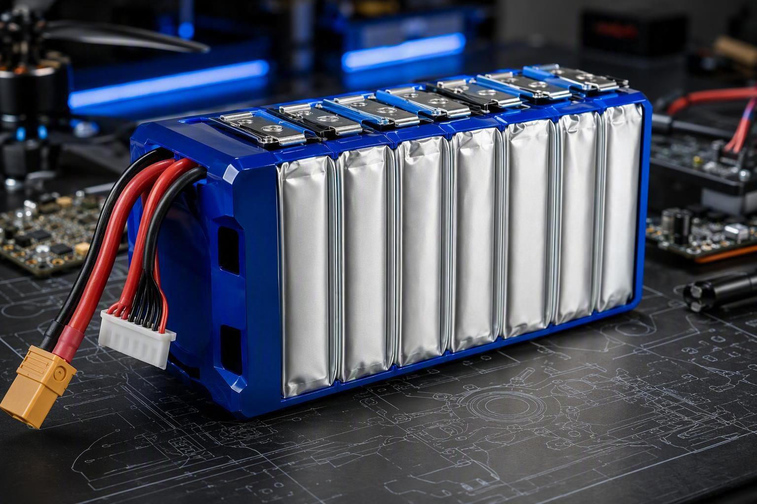
Soft pack is a packaging architecture: stacked electrodes in a laminate pouch, typically requiring external containment and compression. When your airframe has non-standard geometry, that architecture can unlock integration options that are difficult with cylindrical arrays.
Higher space utilization
With soft pack, you can control geometry:
thin-and-wide packs under a payload deck
tall-and-narrow packs in booms or spines
split-pack layouts distributed around a payload bay
When internal volume is “expensive” (hard to enlarge without redesign), reducing dead space can translate into:
more usable energy in the same envelope
the same usable energy with less enclosure/structure overhead
Better weight distribution and CG control
Soft pack doesn’t automatically mean lighter. But it can reduce inactive mass when the pack enclosure and mounting interface are designed as an integrated structure (instead of a separate cage built to fit a standardized module).
More importantly for OEM leads: better CG and packaging freedom reduces late-stage “battery-driven” compromises.
That matters because payload, avionics, and battery placement often shift during development. If the pack geometry is flexible, you’re less likely to discover in EVT/DVT that the only viable fix is an airframe redesign.
Faster mechanical integration
Soft pack architecture is most valuable when you want to design around:
CG line placement (instead of “where a brick fits”)
mounting hardpoints (instead of adding secondary structure)
cooling path (instead of hoping the bay convects)
swap workflow (connector orientation and access that reduce field errors)
Soft pack reliability depends on pack engineering
A pouch cell without proper containment is mechanically vulnerable.
The correction is simple: Reliability comes from cell quality + pack engineering + validation, not the casing label.
For an OEM power-system lead, the practical question is: what does “pack engineering” change for the aircraft?
A soft pack only becomes a reliable UAV solution when the supplier controls mechanical and thermal constraints that show up in daily operation:
Dimensional stability over cycle life so the pack keeps fitting the bay, holding compression, and maintaining predictable electrical performance.
Vibration and shock resistance so the internal stack, tabs, and routing don’t drift into high-resistance joints or intermittent faults.
Connector and harness reliability so swap workflows don’t turn into field error rates and connector RMAs.
Thermal consistency so peak-power phases don’t force derating, payload cuts, or conservative mission profiles.
Warning: A custom-shaped pouch pack without engineered containment, edge protection, and strain relief is a fast path to field failures that get misdiagnosed as chemistry issues.
When should UAV OEMs choose soft pack architecture?
Soft pack is worth serious evaluation when at least one of these is true:
Your airframe is geometry-constrained (slender fuselage, wing-root cavity, distributed compartments).
You’re payload-sensitive, and enclosure/mounting overhead materially changes payload margin.
CG control is tight, and you can’t solve offsets with ballast or late-stage rearrangement.
Thermal headroom is a limiter, and you need a defined thermal interface and airflow plan.
You want to reduce EVT/DVT redesign risk when payload, avionics, and battery placement inevitably change.
You need non-standard voltage or split-pack layouts driven by platform architecture.
A simple integration example
A VTOL inspection drone has a narrow fuselage and a forward gimbal. A standardized rigid module forces a rectangular bay, leaving unused volume and pushing the pack aft.
A custom soft pack (with a purpose-built enclosure and compression strategy) can enable:
a flatter profile that uses the fuselage envelope more effectively
pack placement closer to the desired CG line
a mounting interface designed with the bay, not added after the fact
No single change “solves everything.” But when the pack is designed as part of the aircraft, the platform usually becomes easier to balance, easier to cool, easier to service, and easier to iterate—without late-stage surprises.
What to evaluate before selecting a custom soft pack supplier
If you want one phrase that captures the technical risk, it’s this: custom drone battery pack design is both an electrical engineering problem そして a mechanical integration problem.
Treat this as a specification and validation exercise, not a catalog purchase.
Electrical requirements
voltage window and series count limits
usable capacity target (define what “usable” means)
peak vs sustained discharge profile by mission phase
internal resistance measurement conditions (temperature, SOC window)
connector type and orientation (exit face, strain relief, service access)
BMS telemetry requirements (what the aircraft needs to operate safely)
Mechanical and integration requirements
outer dimensions with tolerances and a clear “installed” envelope
mounting scheme and service workflow constraints
enclosure stiffness, edge protection, and ingress protection requirements (dust, moisture)
compression approach and how it is maintained over life
vibration/shock assumptions and isolation strategy
harness routing and strain relief strategy
Thermal requirements
ambient temperature range and heat-soak conditions
thermal interface strategy (conduction plate, airflow channeling, etc.)
allowable temperature rise during peak power phases
Qualification and documentation
validation plan that matches your duty cycle (vibration/shock, thermal cycling, swap wear)
abuse protection verification (external short, overcharge protection via BMS)
transport/compliance documents required for your markets (e.g., UN38.3 where applicable)
A practical decision checklist for evaluating battery architecture cost
Cost / value driver | What to measure | Why architecture affects it | How to estimate |
|---|---|---|---|
Airframe redesign effort | engineering hours + tooling impact | standard modules can force structural/aero changes | track ECNs and CAD rework cycles |
Installed battery system mass | pack + enclosure + mounting + harness | inactive mass reduces payload margin | weigh the installed system, not cells |
Swap/turnaround time | minutes per swap + incident notes | bay access and connector orientation affect uptime | time studies + maintenance logs |
Field failure patterns | incidents per flight-hour / cycle band | mechanical design issues show up as connectors/tabs | RMA + root-cause categories |
Qualification burden | test matrix size + iteration count | custom work needs a clear validation plan | count test articles + iterations |
Next step
If you’re evaluating custom UAV battery pack architecture, choose partners who can translate aircraft constraints into a pack you can actually integrate—and repeat in production. That typically includes requirements capture (envelope, CG constraints, power profile), rapid prototyping with test feedback loops, manufacturing readiness and QC, and documentation and qualification support.
The right UAV battery is not always the one with the highest cell-level energy density. For customized industrial drones, it’s the one that lets the aircraft hit mission requirements within physical and operational constraints.
Soft pack architecture still makes sense when it gives you degrees of freedom that standardized formats can’t—especially when your airframe is geometry-constrained and your platform economics are payload- and uptime-driven.
If you want a starting point for scoping a custom UAV battery architecture, see Herewin drone battery solutions.

 日本語
日本語  English
  Español
  한국어
한국어  Deutsch
  Français
  Русский
  Bahasa Indonesia
  ไทย
ไทย  العربية
  Português do Brasil
  Italiano
  Nederlands