










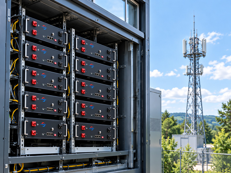





As electric mobility fleets expand, battery packs are no longer treated as individual power units. In battery swapping networks, delivery fleets, and commercial EV applications, each battery represents a high-value operational asset.
Under intensive daily cycling and elevated ambient temperatures, improper State of Charge (SOC) management can significantly accelerate capacity degradation and increase replacement costs. For commercial operators, protecting cell health is not a matter of consumer convenience—it is a core financial strategy that directly dictates Total Cost of Ownership (TCO) and fleet availability.
Why SOC Window Matters in Commercial Battery Operations
The State of Charge (SOC) operating window defines the usable battery range between the upper and lower limits controlled by the Battery Management System (BMS). These operating boundaries are determined by voltage, current, temperature, and safety parameters.
SOC max (Upper Operating Boundary)
Usable Energy Zone (Operating SOC Window)
SOC min (Lower Voltage Cut-off)
In high-utilization commercial environments, the selected SOC window directly governs four critical operational parameters:
Available Energy per Cycle: Determines vehicle range per swap and service radius.
Charging Frequency: Dictates how often packs enter swapping cabinets or fast-charging bays.
Battery Aging Rate: Controls the pace of irreversible capacity fade and internal resistance growth.
Fleet Availability: Governs the number of healthy, ready-to-deploy packs in swapping cabinets.
For commercial operators, the primary goal is not maximum energy extraction from every single charge cycle, but the lowest cost per kilometer over the entire battery lifecycle. By narrowing the effective depth of discharge, operators can dramatically suppress mechanical and electrochemical degradation, trading a minor percentage of single-swap range for significantly extended usable lifecycle cycles.
The Challenge of High-Frequency Battery Swapping Operations
Managing battery health in swapping networks presents operational challenges that standard electric vehicle fleets rarely encounter.
In conventional commercial EVs, the operational cycle follows a predictable sequence:
Drive (Discharge) → Plug-in Charge (Low/Moderate C-rate) → Extended Rest Period (Thermal Normalization)
Standard EVs typically rest overnight or between shifts, giving battery packs hours to dissipate heat and allow internal chemical gradients to normalize.
In high-frequency battery swapping networks, however, the duty cycle is continuous and aggressive:
Rapid Discharge → Instant Swap → Fast Cabinet Charge → Minimal Queue Waiting → Rapid Reuse
Because swapping packs rotate continuously between heavy vehicle discharge and rapid cabinet charging, the battery pack has virtually zero recovery time. Heat generated during high-C discharge in the vehicle accumulates directly into the high-C fast-charging cycle inside the swapping cabinet.
Without active SOC window management, this continuous thermal accumulation rapidly accelerates cell degradation.
Why High Temperature Accelerates Battery Degradation
Temperature and high SOC act synergistically to accelerate battery degradation. Elevated temperatures speed up electrolyte decomposition, Solid Electrolyte Interphase (SEI) layer growth on the anode, and internal resistance buildup. High temperatures also reduce SOC estimation accuracy as cell voltage response becomes less predictable.
When elevated operating temperatures collide with extreme SOC boundaries, specific degradation mechanisms dominate:
High SOC + Elevated Temperature: Sustains high cell potential, accelerating electrolyte oxidation, gas generation, and structural degradation of cathode materials.
Low SOC + Elevated Temperature: Increases internal impedance, triggering localized voltage instability during high-current acceleration and raising the risk of capacity loss during deep discharge.
According to research on thermal and state-of-charge interactions, calendar and cyclic aging rates compound rapidly when batteries remain at high SOC under thermal stress.
For high-utilization fleets operating in hot environments, uncalibrated full-range SOC usage can shorten pack service life significantly.
Why Maximum SOC Range Is Not Always the Best Strategy
A common operational misconception in fleet management is that expanding the usable SOC window to near 100% maximizes profitability by offering drivers maximum range per swap. In high-utilization commercial fleets, maximum immediate range does not equal maximum long-term profitability.
Operational Strategy | Immediate Usable Range | Single-Cycle Energy | Cell Stress Level | Relative Cycle Life Impact | Annualized Asset Depreciation |
|---|---|---|---|---|---|
Full-Range Operation (Near 0%–100% SOC) | 100% (Maximum) | Highest | Severe Voltage & Thermal Stress | Significantly Lower | High (Frequent pack replacement) |
Optimized Window (20%–80% SOC) | ~60% Effective DoD | Moderate | Controlled Chemical & Mechanical Stress | Substantially Extended | Low (Extended asset depreciation) |
Operating cells continuously at 100% SOC exposes cathode materials to sustained high-voltage stress and thermal accumulation during fast charging. Conversely, operating at intermediate SOC ranges (such as 20% to 80% SOC) reduces mechanical stress on graphite anodes during lithium insertion and extraction.
Industry studies on Li-ion degradation mechanisms demonstrate that restricting cycling to intermediate SOC ranges significantly reduces usable capacity loss and impedance growth, effectively extending the practical service life of commercial pouch and prismatic cells under heavy daily utilization.
Recommended SOC Windows for Different Battery Chemistries
Optimal SOC limits depend heavily on cell chemistry. LFP and NMC chemistries exhibit fundamentally different crystal structures, thermal runaway thresholds, and voltage response curves.
Chimie des batteries | Typical Recommended High-Utilization SOC Range | Primary Thermal & Operational Stress Drivers | Key Operational Consideration |
|---|---|---|---|
Phosphate de fer lithié (LFP) | 20% – 85% | Lithium plating risks under deep discharge; accelerated SEI growth under heat | Highly stable crystal structure; periodic full-charge calibration may be required to correct SOC estimation drift caused by the flat voltage profile. |
Nickel Manganese Cobalt (NMC) | 30% – 80% | High-voltage electrolyte oxidation; elevated thermal sensitivity | High energy density; highly sensitive to high SOC states under elevated ambient temperatures. |
The SOC ranges listed above represent baseline engineering guidelines. Actual operational limits should always be validated through empirical battery cycle testing, localized ambient thermal profiling, and hardware BMS calibration.
Dynamic SOC Adjustment Based on Operating Temperature
Static SOC boundaries fail when environmental conditions change. A static 85% upper SOC limit that protects an LFP pack at 22°C ambient temperature may accelerate capacity degradation when cabinet temperatures exceed 40°C during peak summer swapping hours.
Commercial operators should implement an adaptive SOC strategy governed by real-time telemetry:
Battery Operating Temperature | Dynamic SOC Strategy | Charging & Operational Controls |
|---|---|---|
Below 35°C | Standard Operating Window (e.g., LFP 20%–85% / NMC 30%–80%) | Normal charging strategy maintained according to battery specifications. |
35°C – 45°C | Moderately Restricted Window (e.g., Upper SOC capped at 75%–80%) | Gradually reduce fast-charging current; enable forced cabinet fan cooling. |
Above 45°C | Restrictive Safety Window (e.g., further restrict SOC limits according to thermal conditions and battery specifications, reducing the upper SOC boundary toward 70%) | Restrict C-rate charging; enforce mandatory cabinet cooling hold before re-issuing pack. |
Implementing dynamic temperature-aware derating prevents thermal runaway triggers and minimizes calendar aging while packs wait in swapping bays during high-temperature hours.
How Smart BMS Enables Dynamic SOC Management
Executing an adaptive SOC control policy across hundreds or thousands of distributed swapping packs requires an intelligent battery management system for fleet operations integrated with cabinet charging infrastructure.
An industrial-grade Smart BMS provides five core functions essential for high-frequency swapping networks:
Temperature-Compensated SOC Estimation: Adjusts SOC calculation algorithms dynamically based on real-time cell temperature sensors to prevent hidden overcharging.
SOC Accuracy Calibration: Periodically recalibrates SOC estimation through voltage mapping, coulomb counting, and SOH compensation to correct estimation drift.
Adaptive Charging Current Control: Communicates directly with cabinet chargers via CAN/RS485 protocols to adjust charge current as cell temperatures rise.
Cycle History & Coulombic Analysis: Tracks cumulative throughput and SOC residence time to adjust voltage thresholds as cells age.
SOH-Based Capacity Calibration: Recalibrates usable SOC windows based on State of Health (SOH) degradation to ensure balanced pack aging across the fleet.
Cloud Telemetry Integration: Transmits cell-level data to fleet management dashboards for predictive maintenance and automated asset triage.
What Fleet Operators Should Look for in Battery Suppliers
Implementing dynamic SOC control requires seamless coordination between hardware, firmware, and cell chemistry. When selecting a commercial battery manufacturer for high-frequency swapping applications, fleet procurement teams and OEM engineering managers should evaluate:
Custom BMS Firmware Adaptability: Can the supplier modify CAN/RS485 communication protocols and SOC algorithms to integrate directly with your swapping cabinet chargers?
Thermal & Enclosure Engineering: Does the battery pack design incorporate localized thermal dissipation channels suited for continuous fast charging?
Validation & Cycle Data: Can the manufacturer provide empirical degradation curves under high ambient temperatures and aggressive C-rates matching your operational profile?
As a vertically integrated battery cell and pack manufacturer, Herewin collaborates with commercial operators and OEMs to engineer custom lithium battery pack architectures equipped with smart BMS firmware solutions optimized specifically for commercial EV and battery swapping operations.
Maximizing Fleet ROI Through Dynamic Battery Optimization
Transitioning from static, full-range charging to a dynamic, temperature-compensated SOC strategy transforms battery management from a routine maintenance task into a high-impact financial lever. By controlling cell stress and suppressing capacity fade, commercial fleet operators can directly lower annualized replacement CAPEX, extend pack service life, and maximize swapping cabinet availability.
For example, a high-utilization delivery fleet operating in hot summer conditions using an uncalibrated 0%–100% SOC window experiences rapid capacity fade. Implementing an adaptive SOC window—such as a 20%–80% baseline capped at lower upper thresholds above 35°C—protects cell chemistry, extending service life and improving long-term asset ROI.
Executing these dynamic control strategies requires seamless coordination between hardware, firmware, and cell chemistry. Partnering with a vertically integrated battery manufacturer ensures that your BMS firmware, thermal enclosures, and cell selection are custom-engineered for high-frequency operations.
To evaluate how custom battery architecture and intelligent BMS solutions can optimize your total cost of ownership, contact Herewin to discuss customized battery pack solutions for high-cycle commercial applications.





 Français
  English
  Español
  한국어
한국어  Deutsch
  日本語
日本語  Русский
  Bahasa Indonesia
  ไทย
ไทย  العربية
  Português do Brasil
  Italiano
  Nederlands