






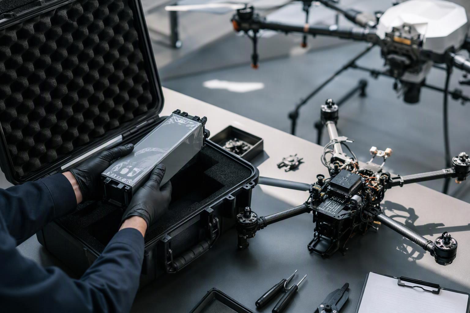
Semi-solid UAV battery specifications can be difficult to compare when suppliers report different product levels, test conditions or development stages. Before requesting quotes, establish what each figure describes, what evidence supports it, and which aircraft requirements the proposed pack must meet. The checklist runs in seven steps, each building on the last: define the product, prepare the RFQ, compare cell- and pack-level figures, verify performance claims, review safety evidence, confirm system integration and lock down production consistency. Where regulations, applicable standards or contract terms require independent verification, obtain the relevant third-party evidence. For other performance claims, supplier-generated test records may be sufficient if the methods, sample basis and results are disclosed and can be independently reviewed by the buyer.
Define ‘semi-solid’ before comparing quotes
“Semi-solid” describes a cell architecture, not a guaranteed level of performance. Before comparing offers, ask each supplier to document six items: the product level covered by each specification, the measurement basis, the intended application and market, the architecture described as semi-solid, the current development stage, and responsibility for supplying, designing and supporting the cell, pack, BMS and charger. Require the supplier to declare its development stage using a clear set of labels — research-stage sample, engineering sample, pilot-production unit or production-qualified product — rather than treating these as fixed industry-wide categories.
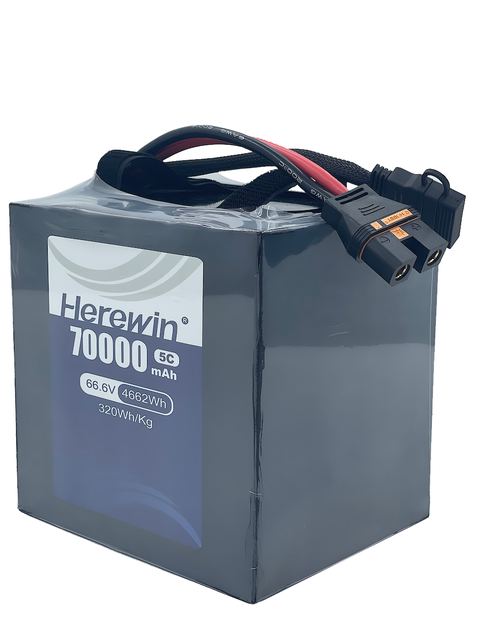
Comparability starts with the energy-density figures. If one document gives a headline range and another lists a different value, check whether both describe the same product level and measurement method. A cell-level figure cannot be compared with a pack-level figure, even when both are expressed in Wh/kg.
Calling a cell “semi-solid” does not by itself determine which safety standard applies; applicability depends on what the product is, how it is used, which market it targets, and whether the scope of a given standard actually covers it. IEC 62133-2:2017, as amended by Amendment 1:2021, addresses the safety of portable sealed secondary lithium cells and batteries under intended use and reasonably foreseeable misuse. IEC 62619:2022 covers secondary lithium cells and batteries used in industrial applications, including specified stationary and motive applications, while explicitly excluding road vehicles, which fall under the IEC 62660 series. Neither standard should be assumed to apply to a UAV battery just because it is lithium-based or used in an industrial setting. Ask the supplier to identify the standard it applied, explain the basis for that choice, and name the product configuration covered. Confirm the compliance requirements of your target market and aircraft programme, and write the intended use into the requirement sheet before anyone quotes a certificate.
Turn your flight profile into a requirement sheet
Prepare the requirement sheet before requesting quotes. For each performance item, specify the value, unit, operating conditions and acceptance criteria, then ask suppliers to provide the corresponding data or test records. Organise the sheet into six blocks, separating buyer-defined requirements from the data and records each supplier must provide.
Block | What the buyer defines | What the supplier must provide |
|---|---|---|
Electrical | Nominal voltage, capacity, continuous and peak discharge requirements, charge rate, voltage limits, and measured aircraft load profile | Current-time curves, terminal voltage, temperature rise, test conditions and supporting records |
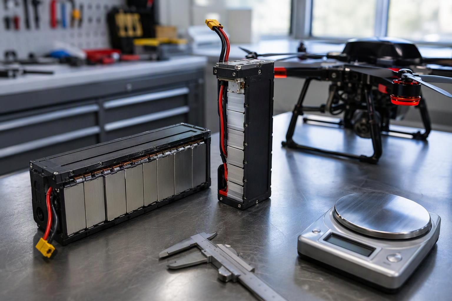
Mechanical | Mass budget, dimensions, mounting pattern, connector position and harness requirements | Dimensioned drawing, actual sample mass and dimensional inspection records |
Environmental | Operating temperature and humidity, vibration and other programme-specific conditions, applicable test specification and acceptance criteria | Test method, conditions, results and pass/fail assessment against the agreed specification |
Integration | Required BMS protocol, telemetry fields, charger behaviour and protection strategy | Interface documentation, communication test records and charger specifications |
Quality | Lot traceability, end-of-line inspection, sample-to-production consistency and qualification-changing events | Batch records, inspection criteria, non-conformance procedures and change-control commitments |
Commercial | MOQ, lead time, warranty and technical-document delivery requirements | Quotation terms, delivery schedule, warranty scope and agreed change-control terms |
Environmental requirements and production-quality controls need particular attention. Specify the applicable vibration profile, test specification and acceptance criteria, and require the supplier to show how its test conditions relate to the aircraft programme’s defined requirements. Define lot-traceability and production-consistency requirements in the initial RFQ: if they are introduced only after sample approval, suppliers may not have agreed to the data and controls needed for production release.
The electrical block is one of the easiest places for an RFQ to leave critical requirements undefined. For cycle life, specify the test conditions, sample basis and end-of-life definition required in the RFQ. A cycle count alone is not enough to compare suppliers or predict service life; the section on verifying performance claims explains which records to request and how to assess them.
One electrical requirement needs to be defined from the aircraft’s operating data: peak current. Set it from the aircraft’s measured load profile, not the supplier’s headline C-rate. Record the current magnitude and pulse duration under representative conditions — spray-pump inrush or a climb burst — along with the minimum allowable pack-terminal voltage and temperature rise. Include this load envelope in the RFQ so suppliers can size and test the pack against the aircraft’s actual operating demands.
Compare cell-level and pack-level Wh/kg
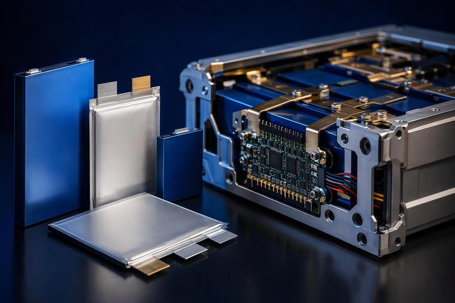
Cell-level energy density does not translate directly into pack-level energy density. In NASA’s X-57 reference design, a nominal cell-level specific energy of 225 Wh/kg corresponded to a nominal pack-level value of 149 Wh/kg, a ratio of approximately 66% (NASA NTRS, cell-to-pack scaling trends). This ratio illustrates the gap in one aviation battery design; it should not be used as a conversion factor for agricultural UAV packs, because the ratio depends on the pack’s structure, thermal management, protection systems, connectors and the safety provisions the programme requires.
Ask whether the pack-level figure is measured, by whom, on what configuration, and which components the calculation includes. There is no universal pack-level Wh/kg target for all UAVs. Set the target against the aircraft’s payload, flight profile, installation limits, thermal requirements and safety margins, then compare suppliers on the same pack-level measurement boundary.
Verify cycle-life, C-rate and fast-charge claims
Two cycle-life reports can both say “1,500 cycles” and still not be comparable. Differences in depth of discharge, temperature, charge rate or discharge rate change the measured degradation rate, so request the full test protocol, capacity-retention curve, DCIR trend, sample count and batch information rather than a headline cycle count. Define the end-of-life threshold by your application, warranty terms or an agreed test protocol.
Continuous and peak C-rates describe different operating conditions. A peak rating does not establish sustained discharge capability, so request the pulse duration, ambient temperature and voltage limits associated with each rating. A flight-time figure cannot be compared reliably across suppliers without a stated payload, mission profile, ambient temperature and a clear indication of whether the result was measured or modelled.
For a stated 3C–5C fast-charge capability, request results from a defined charging protocol, including the permitted temperature range, capacity retention and cycle life measured under the same charging conditions. Request the test data behind any fast-charge claim before treating the rate as confirmed.
Separate safety evidence from transport compliance
UN 38.3 addresses the design tests used to assess lithium cells and batteries for transport. Passing these tests does not establish compliance with every packaging, marking, documentation or shipment requirement, and it does not by itself demonstrate that a pack is safe for a particular UAV duty cycle. Treat transport-test evidence and in-flight safety validation as two separate reviews.
Request the UN 38.3 test summary that corresponds to the exact model and configuration you are buying. Check that the summary identifies the cell or battery type you are buying, includes the required report details and test results, and cites the applicable edition of the UN Manual of Tests and Criteria (UN Manual of Tests and Criteria, Rev.8 and Amendment 1, UNECE). Confirm that the cited edition is accepted under the transport rules applicable to your shipping route. The UN 38.3 test summary is a required summary document, not a replacement for the full test report, so request the full report whenever the summary does not resolve a material question.
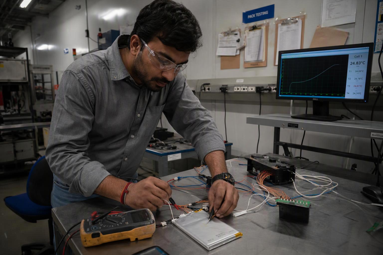
Application safety means abuse testing: deliberately driving a cell, module or pack beyond normal operating limits to characterise failure behaviour. Potential electrical abuse scenarios include overcharge, forced discharge, external short circuit and internal short circuit. The applicable test programme should be defined according to the product design, the identified hazards and the relevant standards, rather than applying one fixed set to every pack. For each test, check that the report identifies the test object (cell, module or pack), the method, the conditions, the observed failure behaviour and the acceptance criteria. Without the test-object information, it may be impossible to determine whether the result applies to the finished pack. Internal short circuit requires particular attention: it depends on a specific trigger method and protocol, so a claim that it was tested is not sufficient without the method and conditions.
For mechanical abuse, select test methods and acceptance criteria that match the cell format, pack enclosure and intended failure scenarios rather than copying one fixed parameter set. A published recommended practice such as Sandia’s SAND2017-6925 — written for electric-vehicle energy-storage systems — may provide a useful reference for selecting or understanding test methods, provided its scope and limitations are taken into account; its endpoints are scoped to that context and do not amount to a certification basis for a drone pack. Ask the supplier to identify the test standard, the assembly level, the conditions, the observed failure behaviour and the post-test monitoring criteria. A cell-level test cannot, by itself, establish the behaviour of the finished pack.
Evidence stream | What the evidence can establish | What still needs verification |
|---|---|---|
UN 38.3 test summary | The identified cell or battery type has the relevant transport design-test evidence | Exact model and configuration, applicable revision, required summary fields and shipment-specific compliance |
Electrical abuse testing | Observed failure behaviour under the specified electrical abuse conditions | Test object, method, conditions, reported hazards, monitoring period and acceptance criteria |
Mechanical abuse testing | Observed behaviour under the specified mechanical abuse conditions | Test method, assembly level, conditions, failure behaviour and suitability for the intended application |
Testing against an applicable IEC standard | Results against the specified test requirements for the identified product and configuration | Edition, exact model and configuration, product level, applicable clauses and official certification evidence |
UL certification or listing | Certification status and scope for the identified product or component | Standard and edition, certification scope, exact model and configuration, and components not covered |
For IEC or UL evidence, identify the applicable standard and edition, then verify the scope against the official standard or certification record. Check the exact model, configuration, product level and applicable clauses the evidence covers. A test report, a declaration of conformity and a UL certification or listing are not interchangeable, and an industrial or portable label alone does not settle which standard applies. If thermal-runaway or thermal-propagation evidence is required, request the relevant test report and the standard, method and assembly level used.
For each certificate or test report, request the standard and edition, the test or certification scope, the exact model and configuration covered, and any relevant exclusions. Cell-level certification does not establish that the finished pack, its BMS, enclosure, connectors, charger or integration with the aircraft has been assessed to the same standard or scope.
Validate BMS, telemetry, charger and mechanical fit
“Supports CAN” is not a requirement; a named message with named fields and units is. Whichever protocol is used — DroneCAN’s standard battery message or Smart Battery Data — confirm that it matches your flight controller and that the supplier documents the implemented fields, units, sign conventions, update rate and error behaviour. For a fuller comparison of these interfaces, see our overview of drone BMS communication protocols. The Smart Battery Data specification is a good example of a protocol where the bar is higher than a name — it defines required and optional command codes, so require the supplier to state which revision and which codes it implements rather than assuming the full set. Keep the field-level tables in your RFQ template or a technical appendix.
Split the work into two phases, because some checks can be done on paper and others need hardware in hand.
Before samples ship — document and rig checks:
Protocol match: the BMS speaks the protocol your flight controller expects, at a compatible revision.
Field completeness: every field your autopilot consumes is present, with units, sign and update rate stated.
Error handling: documented behaviour for hot, cold, overload, bad battery and BMS-error states.
Interface documentation: review the interface specification, dimensional drawing and charger specification. Where hardware is not yet available, use a simulator or test fixture to check the documented communication behaviour.
After samples arrive — physical and on-aircraft checks:
Physical conformity: measured mass, three-dimensional dimensions, mounting hole pattern, connector position and harness length against your drawing.
Integration test: BMS data verified on the target aircraft or an equivalent rig, including what happens on a communication dropout.
Failure response: how the system behaves when data is missing, stale or out of range.
System validation: voltage sag, temperature rise, communication faults and low-voltage warnings checked under representative load.
Integration note: “UART supported” describes the serial communication interface, not the battery’s application-level protocol. Request the message format, field definitions and error-handling behaviour as well.
Beyond protocol compatibility, check the pack’s effect on aircraft mass and centre of gravity, the mounting and harness arrangement, and the charger’s voltage, current and termination behaviour. Confirm how the BMS and charger interact where required, and test the assembled system under representative loads before approving the design.
Plan sample acceptance and production release
Passing a prototype test does not establish production consistency. Capacity and internal-resistance variation between cells can affect usable pack capacity, current distribution and voltage sag, and the impact depends on pack topology, BMS control, interconnect resistance and the aircraft’s load profile, so the acceptance plan should define measurable limits and verify them against production data before releasing the design.
Request supporting records rather than assurances: cell-lot distributions for capacity and DCIR or ACIR with stated acceptance limits and outlier handling, pack-to-cell-lot traceability, weld and crimp parameters with inspection records, rework rules, and end-of-line test records. Define the pilot-lot size, sampling plan and acceptance limits before production validation, and release production only when the agreed criteria are met and the data provide sufficient evidence of consistency across the required lots.
Define change-control requirements before qualification. A change to the cell, BMS, pack construction or manufacturing process may affect transport-test applicability, pack-level validation or the aircraft programme’s approval status. Agree in writing which changes require notification, documented assessment, additional testing or formal re-approval. Require traceability by model, revision, factory and lot so that the delivered configuration can be checked against the approved design. Where a change affects transport-test applicability, check the relevant shipping requirements, such as 49 CFR 173.185 for US-bound shipments.
FAQ
What should a drone OEM request before approving a semi-solid battery sample?
Ask for a sample-to-drawing conformity check, the test conditions behind every performance figure, and the safety evidence that applies to the exact configuration. Review the interface documents before shipment, then check BMS communication, low-voltage warnings and voltage sag under representative loads once the sample is available.
Can cell-level test data qualify a finished UAV battery pack?
No. Cell-level results describe the cell, not the assembled pack. Pack construction adds structural components, interconnects, protection and BMS functions that can affect system-level performance and safety. Treat cell data as an input and require pack-level evidence for pack-level claims.
What should happen if a supplier changes the cell, BMS or pack design after qualification?
Require written notification of relevant design or process changes. The agreed change-control procedure should determine whether each change needs a documented assessment, additional testing or formal re-approval. In every case the supplier must keep the model, revision, factory and lot traceable in delivery.
Before requesting quotes, define the aircraft’s duty cycle, pack-level requirements and acceptance criteria. Suppliers can then be evaluated against the same operating conditions and evidence requirements, rather than against headline specifications that may describe different products or test conditions.
Separate from the battery checklist above, one US-market reminder is worth flagging. If your programme targets the United States, review supply-chain provenance on its own: FCC Covered List rules may affect whether certain UAS or critical components — including batteries and BMS — can obtain the authorizations needed for US import, marketing or sale. The outcome depends on the specific rule, product, supplier entities and any applicable waiver, so check the current FCC requirements for your product and sales pathway, and keep origin and manufacturing records traceable by model, revision, factory and lot.

 Français
 English
 Español
 한국어
 Deutsch
 日本語
 Русский
 Bahasa Indonesia
 ไทย
 العربية
 Português do Brasil
 Italiano
 Nederlands