










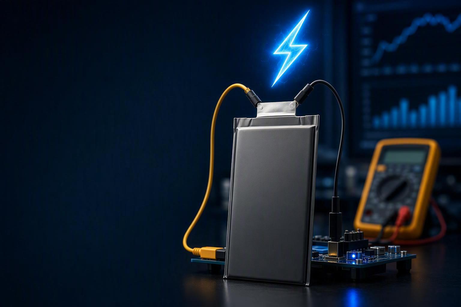
A supplier says a UAV lithium battery cell supports 5C charging. A demo run tops the pack up quickly. Does that prove it is a 5C fast-charge cell?
Not on its own. The real question a buyer has to answer is whether the cell can do more than accept a high current once — and keep doing it. Can it hold that rate cycle after cycle? Does temperature stay under control while it does? Does internal resistance stay stable after repeated fast-charge cycles? Does capacity hold, does the pouch stop swelling, and does the cell still serve the mission after 400 or 500 cycles?
This article walks through the verification chain a procurement or integration team can use to judge whether a datasheet 3C or 5C claim is worth trusting: claim → test conditions → temperature rise → DCIR growth → capacity retention → physical condition → cycle life → acceptance.
Keep the object of verification clear from the start: the datasheet claim is a cell-level statement. Verify that level first, then confirm pack-level behavior — thermal consistency and cell-to-cell spread — and only then judge the battery on the mission. In short: cell claim → cell test → pack integration → mission validation.
“5C fast charging” is not a complete specification. It becomes auditable only when you fix the conditions under which it was demonstrated — and then verify that the cell holds up across repeated cycles.
What Does 3C or 5C Fast Charging Actually Mean?
Before a single measurement makes sense, pin down what the C-rate label actually claims. C-rate expresses charge current relative to capacity:
Charge current = Battery capacity × C-rate
For a 5 Ah cell:
1C = 5 A
3C = 15 A
5C = 25 A
A cell that tolerates 5C charging is not automatically suitable for a UAV application; its charge capability still has to be evaluated alongside discharge demand, pack configuration, and cell-to-cell consistency.
A 3C rate corresponds to roughly 20 minutes of theoretical constant-current charging, while a 5C rate corresponds to roughly 12 minutes, before the CV taper is considered. That is the key point where many claims go wrong: those numbers describe the constant-current (CC) stage, not the time to a full charge. Charging ends with a constant-voltage (CV) tail during which current tapers down, and that tail can take a large share of the total charge time. As BatteryMBA’s explanation of CC-CV charging notes, the actual full-charge time is CC time plus CV taper time, and it is always longer than the simple capacity/current calculation.
So a claim should never be read as “3C = 20-minute full charge.” A more defensible reading is “the cell can be charged at 3C during the constant-current phase under specified conditions,” with the actual charge time left to the CC-CV profile, cutoff voltage, temperature, and chemistry. Charge-rate capability is meaningless unless those conditions — reference temperature, starting and ending SOC, and cutoff — are pinned down.
How to Verify the Charging Conditions Before Testing
The most common reason a “5C test” is not credible is that the conditions were never defined. Before you measure temperature or DCIR, you have to know exactly what was tested. This guide focuses on UAV lithium-polymer (LiPo) cells — the same verification logic applies to other chemistries, but each system brings its own conditions and limits. Either way, the claim is not auditable until you can answer every row in this table.
Test item | Must be defined |
|---|---|
Cell chemistry | UAV LiPo focus; other systems need their own conditions |
Nominal capacity | Ah |
Charge rate | 1C / 3C / 5C |
Charge profile | CC-CV (and the CV cut-off current) |
Charge cutoff voltage | Manufacturer specification |
Ambient temperature | Controlled |
Rest time | Before and after charge |
Discharge rate | Defined |
Measurement points | Where temperature / voltage were logged |
A valid “fast charge” claim should specify starting and ending SOC, target time, temperature, fresh versus aged condition, voltage limit, and a capacity-retention target. If the supplier cannot state these, the number is a marketing figure, not a specification.
Temperature Rise — The First Test of Real Fast-Charge Capability
Higher charge current generates more heat, and that heat is the first stress the cell has to absorb. Temperature rise is therefore the first observable check on a fast-charge claim. Temperature stability is often what separates a credible fast-charge claim from an overstated one.
What to measure:
starting temperature
peak temperature during the charge
temperature rise over ambient
cell-to-cell temperature difference across a pack
any local hot spots
Keep the two levels distinct. At the cell level, the question is whether one cell stays within a thermal limit during charging. At the pack level, the question shifts to the spread across cells in a series string — how far apart their temperatures get under the same charge current. Both levels matter, but a supplier may only present the clean single-cell number and leave the pack-level spread unmeasured. In a multi-cell UAV pack, this spread is not a side detail: one hotter cell can age differently from the rest of the series string.
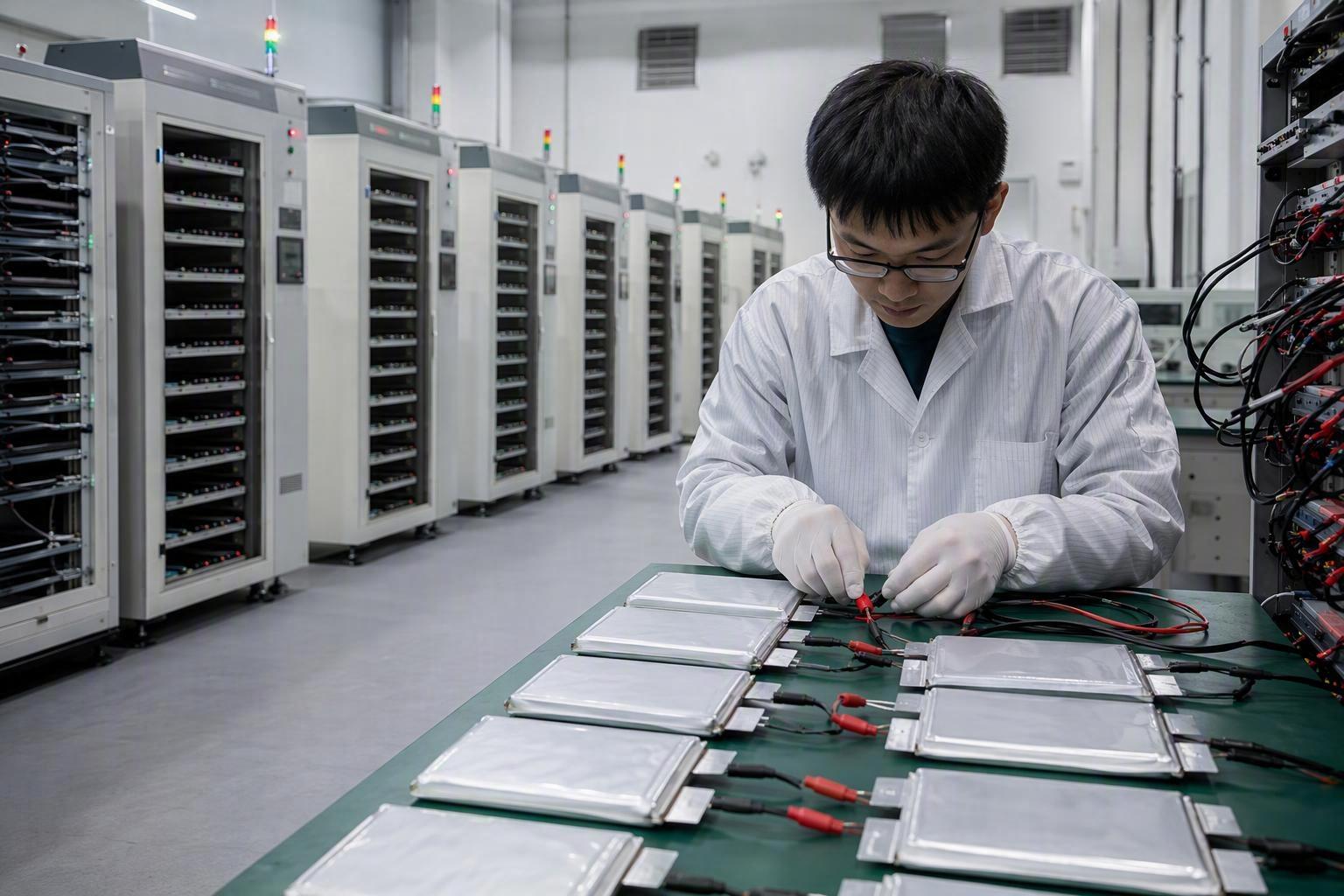
All of this is why a cell-level result does not by itself prove pack-level thermal consistency. A practical setup is a temperature-controlled environment (commonly 25°C) with thermocouples on the cell center and the positive and negative tabs, logged continuously. The goal is not to chase a single fixed threshold but to confirm the rise is stable: no rapid temperature acceleration, no abnormal hot spot, and a cell-to-cell spread that stays within what the cell manufacturer specifies and the pack design allows.
Treat numeric limits as project acceptance criteria, not universal industry standards. The actual limits should be justified against the cell specification, pack thermal design, charging profile, and mission temperature range.
Example: Thermal acceptance criteria for a UAV project
For example, a UAV battery program might define the following internal thermal acceptance window.
Configuration | Peak temp at 3C | Peak temp at 5C | Maximum cell-to-cell spread |
|---|---|---|---|
4S | ≤42°C | ≤48°C | ≤6°C |
6S | ≤44°C | ≤49°C | ≤6°C |
DCIR — Does Fast Charging Accelerate Internal Resistance Growth?
Fast charging is not only about whether the cell can accept the current today; it is about whether many fast-charge cycles damage it over time. Direct-current internal resistance (DCIR) is one of the key indicators used to track changes in cell resistance and degradation under repeated fast charging.
Fast-charge stress can accelerate interfacial degradation, side reactions, and lithium-plating-related damage, which may appear later as rising DCIR.
DCIR is measured with a defined pulse — commonly a discharge pulse of roughly 10 seconds at a fixed SOC and temperature — by dividing the immediate voltage response by the applied current. The practical verification is to measure DCIR at a defined condition and then repeat the measurement at set cycle intervals, for example at 0, 100, 300, and 500 cycles, and compare the growth.
If DCIR climbs rapidly under 3C–5C charging, the cell is experiencing more internal stress under high-rate charge than a stable cell would. In a series pack, evaluate both the absolute DCIR and the cell-to-cell deviation rather than relying on the pack average alone — a single high-resistance cell can dominate the string even when the average looks fine. Our separate cell-acceptance guidance stresses that distribution, not one best cell, drives fleet reliability.
As with temperature, frame DCIR thresholds as project acceptance criteria. A project may define a maximum allowable DCIR increase and a maximum cell-to-cell deviation based on its power requirements — for example keeping DCIR growth below a set percentage after a defined number of fast-charge cycles — but the value and the method should be explicit and agreed.
Example: DCIR growth over a 500-cycle fast-charge test
As an illustrative project dataset, a UAV battery program could compare DCIR growth after 500 cycles as follows:
Charge condition | Example DCIR growth |
|---|---|
1C | 8–12% |
3C | 18–25% |
5C | 30–35% |
Poor-performing 5C claim | >55% |
These figures are illustrative test data, not universal industry benchmarks. The purpose is to show the trend a buyer should look for: a cell that accepts 5C initially but experiences rapid DCIR growth over repeated cycles may not be suitable for a high-frequency UAV duty cycle.
Capacity Retention — Does the Cell Still Deliver Useful Energy After Fast Charging?
The next question is whether fast charging is trading away usable life. The check is simple: measure capacity at a defined reference rate, cycle under the real fast-charge protocol, and re-measure capacity at set intervals.
Capacity retention = remaining capacity / initial capacity × 100%
A single fast-charge demo can pass while the same cell loses unacceptable capacity after repeated fast cycles.
In a series-connected UAV pack, uneven capacity fade can matter as much as average capacity loss because the weakest cell can reach the charge or discharge limit first.
The acceptable retention target depends on the mission and the required service life, so it should not be treated as a fixed universal cutoff — and it should be locked in before the test, not decided after the results arrive. A retention number you choose after cycling is just a rationalization of whatever the cell happened to do.
Example: Capacity-retention targets for a UAV fast-charge program
For example, a UAV program might set the following internal targets.
Charge condition | Example capacity retention after 500 cycles |
|---|---|
1C | ≥92% |
3C | ≥85% |
5C | ≥80% |
These are example project targets rather than universal UAV industry requirements. The appropriate retention target should be determined by the mission’s required service life, payload, flight-time margin, and battery replacement economics.
For high-frequency UAV operations, the supplier should be able to provide a defined capacity-retention target after a specified number of fast-charge cycles — the same discipline we apply when analyzing why drone battery SOC drops suddenly during flight, where dynamic bench and real-flight behavior diverge.
Physical Condition — Check for Swelling and Other Abnormalities
Pouch cells have no rigid case, so they are the format where dimensional change matters most. Fast charging increases electrochemical and thermal stress, which in some conditions can accelerate side reactions, impedance growth, lithium plating, and gas generation. Abnormal gas generation can cause the pouch to swell — an observable sign that warrants attention.
Inspection should cover:
visual swelling and pouch deformation
thickness change measured under a defined condition
edge bubbles and corner distortion
leakage or abnormal odor
Pouch-cell dimensional change is partly reversible (normal expansion during intercalation) and partly irreversible (gas generation), so a meaningful check measures thickness at consistent points and compares change across cycles. IEST’s pouch-cell swelling reference e Frontiers’ analysis of gas generation in pouch cells both describe why persistent cycle-to-cycle growth is more concerning than a one-time formation change.
There is no universal “acceptable swelling” percentage across all pouch cells. A project may define a maximum allowable thickness increase as part of its supplier acceptance criteria, but it should be tied to the cell maker’s own dimensional tolerance rather than treated as an industry norm.
For example, a UAV project might define an internal criterion of no visible swelling and no more than 3% thickness increase after 500 fast-charge cycles, measured at consistent points and under consistent conditions. This 3% figure is a project-specific example, not a universal pouch-cell limit.
Cycle-Life Validation
Temperature, DCIR, capacity, and swelling are process indicators. The final question is whether the battery can still do its job after repeated fast charging.
The right way to answer this is to age the cell under the intended fast-charge protocol rather than a generic slow-charge cycle.
A credible validation repeats: fast charge → rest → discharge → rest, and records capacity, DCIR, temperature, voltage consistency, and physical condition at defined intervals — until a predefined end-of-life criterion is met, which may include capacity retention, DCIR growth, thermal behavior, cell-to-cell consistency, or other mission-specific limits. This mirrors the logic of an industrial cell acceptance workflow, where set intervals and pre-defined limits keep fleet behavior predictable.
For UAV missions exposed to changing field conditions, the validation should also include the temperature range and duty cycle expected in actual operation rather than relying only on a 25°C laboratory cycle.
End-of-life is not a single fixed number. One project’s acceptable EOL threshold may differ from another’s based on mission criticality and fleet economics — so it has to be locked in as a project-specific target before testing.
As an example, a UAV program might define a minimum service-life target of:
≥500 fast-charge cycles for 3C charging
≥400 fast-charge cycles for 5C charging
These are example project requirements, not universal industry limits. The reasoning is simple: a higher charge rate usually warrants a different service-life expectation, and that distinction is part of what a procurement team should pin down. As with every other criterion here, the target should be defined before testing rather than treated as a universal figure.
What Should a Supplier Prove Before You Accept a 3C–5C Battery?
This checklist consolidates the verification chain into a Supplier Acceptance Test a buyer can run directly. Note which rows are cell-level data (charge conditions, DCIR, capacity, and swelling on a single cell) and which are pack-level (thermal spread and cell-to-cell distribution across a lot) — a supplier may only hold one level and pass it off as proof of the other.
The following values are an illustrative project acceptance framework, not universal UAV industry standards. Actual limits should be agreed with the supplier and derived from the cell specification, pack design, mission profile, and test conditions.
Validation item | Example project acceptance criterion |
|---|---|
Charge rate | Claimed 3C / 5C rate verified under a defined CC-CV profile |
Peak cell temperature — 4S | ≤42°C at 3C; ≤48°C at 5C |
Peak cell temperature — 6S | ≤44°C at 3C; ≤49°C at 5C |
Cell-to-cell temperature spread | ≤6°C |
DCIR growth | ≤35% after 500 fast-charge cycles |
Cell-to-cell DCIR deviation | <5 mΩ under defined conditions |
Capacity retention — 3C | ≥85% after 500 cycles |
Capacity retention — 5C | ≥80% after 500 cycles |
Swelling | No visible swelling; ≤3% thickness increase after 500 cycles |
Cycle life — 3C | ≥500 cycles |
Cycle life — 5C | ≥400 cycles |
Test conditions | Temperature, SOC, cutoff voltage, CC-CV profile, rest time, and sample size defined |
A supplier with an auditable fast-charge claim should be able to provide the charge-current, voltage, temperature, and capacity data behind the datasheet figure — including how the impedance growth and voltage behavior look across many cycles. If those plots are not available, or if the answer to “continuous or peak?” is unclear, the claim has not been proven.
The Decision Chain: When to Accept a 5C Claim
Run the claim through this sequence before accepting it:
Is 5C continuous or peak?
If the supplier specifies 5C only as a peak or short-duration rate, it should not be presented as a continuous 5C charging capability.
Are the test conditions documented?
Chemistry, capacity, profile, cutoff, temperature, rest, sample size.
Does temperature stay controlled?
Stable rise, no hot spots, acceptable cell-to-cell spread.
Does DCIR remain stable?
No rapid growth over repeated fast-charge cycles, acceptable spread.
Does capacity remain acceptable?
Retention holds to the project’s target.
Is there swelling or physical degradation?
No abnormal pouch deformation over the test interval.
Does the cell hold performance to the required cycle count?
It still works after the number of fast-charge cycles the mission demands.
Only if the claim clears all seven steps should it be treated as verified.
Next Steps
The 3C/5C label is a starting point, not proof. Verifying it means fixing the conditions, measuring thermal and electrical behavior over repeated cycles, checking the physical cell, and confirming the cycle life the application needs. If you are validating a fast-charge cell for your own mission, define your acceptance criteria before the test begins and ask the supplier for the data behind the number.
Do not set the pass/fail limits after seeing the results.
At Herewin, we approach fast-charge validation as an engineering exercise rather than a marketing one. When you are qualifying a high-rate cell for a UAV mission, bring the mission data — load profiles, peak currents, and expected duty cycle — and we will run the validation together against your own acceptance criteria. The data that proves the claim, not the label, is the point.




 Italiano
  English
  Español
  한국어
한국어  Deutsch
  Français
  日本語
日本語  Русский
  Bahasa Indonesia
  ไทย
ไทย  العربية
  Português do Brasil
  Nederlands