


AI high-density data centers are starting to look less like “steady IT loads with backup power” and more like power-electronics plants.
In the field, the stress doesn’t come from a single big event. It comes from fast ramps, repeated micro-transients, and the kind of wear that quietly builds up across the whole power chain—often without showing up in design documents.
If you care about AI data center power stability, watch for three early symptoms:
Sub-second load transients at the rack level when GPU workloads synchronize.
Increased UPS cycling and more frequent operation in conditioning modes.
Upstream stress in distribution equipment (PDU/busbar/transformer), where voltage regulation and thermal margins stop feeling “static.”
It’s not always consistent across deployments, but when it shows up, it shows up fast.
That’s why the question has shifted from “capacity” to stability under rapid variation—keeping UPS, distribution, and protection coordination out of edge conditions.
This guide focuses on engineering principles, test planning, and acceptance criteria. It intentionally avoids proprietary customer telemetry or project data. Use your own sub-second measurements and event logs to validate the transient envelope for your site.
What changed: AI loads became a transient problem
Synchronized GPU bursts and high dP/dt
AI training loops and inference pipelines can create coordinated power behavior across many GPUs. When thousands of accelerators shift phases together (compute ↔ communication, idle ↔ ramp), the demand change is both fast and correlated.
In high-density clusters, the “randomness averages out” assumption breaks once the scheduler starts lining work up in large blocks.
The engineering impact is not simply “higher kW.” It’s higher dP/dt—how quickly power changes—and the spectral content of that change. Both can interact with control loops and power-quality limits.
Microsoft’s work on stabilization for AI training datacenters is a helpful way to think about the shift: once load swings are large and frequent, power management turns into a control problem (Microsoft Research, 2025).
For planning, it’s a mistake to model GPU rooms like traditional enterprise IT load where utilization changes slowly and randomness averages out.
Common triggers include job start/stop events (“cold start” behavior), training phase changes across the cluster, inference bursts aligned to user traffic, and scheduling patterns that create repeatable ramps.
Why sub-second behavior breaks “steady IT load” assumptions
Sub-second behavior is where stability gets tested. You can’t average it away, and you can’t spreadsheet your way out of it.
Many “static” electrical design decisions implicitly assume variations occur over seconds or minutes. When variations move into the sub-second range, your constraints change.
A few patterns show up repeatedly:
energy storage sizing (kWh) matters less than power rate (kW) and response time
control loop interaction becomes more likely
protection behavior and selectivity margins can be challenged by transient current profiles
This is different from traditional enterprise workloads, even if the average kW looks similar on paper.
At 50–150 kW/rack (and beyond), distribution runs closer to thermal and voltage-drop limits. Small regulation errors show up as voltage droop, warmer connectors, or “mystery” alarms.
As Vicor notes in its discussion of power disaggregation for high-density compute, alternative distribution architectures are partly driven by the difficulty of managing losses and regulation at extreme density.
Where the power chain hits limits
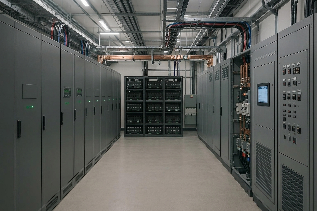
When AI data center power stability becomes a day-to-day transient problem, weak points tend to show up in the same places: UPS control and cycling behavior, distribution thermal/voltage margins, and upstream propagation.
UPS cycling and control boundary
If transients repeatedly trigger correction actions (even if brief), you’ll see more cycling, more thermal stress, and faster wear.
The concern is not that the UPS “can’t supply power.” It’s that dynamic events pull the UPS from standby redundancy into continuous power-conditioning work, which changes how you should evaluate:
inverter/rectifier thermal design margins
control stability under repeated transients
battery cycling profile and calendar/cycle aging interaction
Google’s work on managing distributed UPS energy for power capping is early, but it still makes one point clearly: UPS battery energy can be dispatched to shape facility power, not only to ride through outages (Google Research paper).
Distribution and transformer amplification
When the load swings, current swings. The first signs are usually operational symptoms: connector heating, busbar hot spots, and small but repeatable voltage dips at the rack or row.
Distribution stress also shows up as “soft failures”: rising temperatures, nuisance alarms, degraded power quality, and reduced headroom.
Fast changes at the IT load don’t always stay local. A common failure chain looks like:
GPU transient → PDU/busbar drop → UPS compensation event → upstream current distortion → transformer heating/strain → utility-facing constraints
The broader grid side is becoming a real constraint in high-growth regions. Deloitte’s analysis of AI-driven data center growth highlights concentrated, continuous demand as a stressor that can trigger operational challenges and planning friction (Deloitte Insights, 2025).
Why traditional UPS selection misses the risk
Most “traditional” UPS selection logic is optimized for the backup mission:
support a defined runtime (minutes)
ensure redundancy (N+1 / 2N)
guarantee transfer behavior during outages
manage efficiency at a relatively steady operating point
That works when the load is relatively smooth. When the dominant problem becomes transient stability, the evaluation criteria shift.
Here’s the basic translation: what looks fine at the “average load” level can still behave poorly under repeated transients.
This is where you see the mismatch:
systems sized for peak kW, but not tuned for high dP/dt
batteries specified for runtime, but not for frequent high-rate events
distribution designed for average current, but stressed by ramp-induced peaks
A 2025 arXiv review of AI data centers and grid impacts frames power-electronics-heavy AI compute as a potential driver of stability and power-quality issues, including disturbances and harmonics (arXiv, 2025).
If you only track average kW and monthly PUE, you’ll miss the problem.
You need time-domain visibility:
rack/row power telemetry with sub-second resolution
voltage sag/overshoot statistics (not only RMS averages)
UPS event logs correlated to workload events
distribution thermal cycling indicators
The transient buffering requirement: what “good” looks like
For AI data center power stability, it helps to separate energy from power rate. Transient stability is about absorbing or releasing energy over very short windows.
Functional requirement
A transient buffer component must be able to:
absorb load spikes (or fill load drops) on the time scale that matters to the UPS/control system
reduce the frequency and amplitude of UPS compensation events
keep distribution within tolerable voltage-drop and thermal cycling boundaries
Decision triggers: when a transient buffer stops being “optional”
To decide whether transient buffering belongs in scope, use a simple X/Y/Z test (fill these in from your own telemetry and acceptance criteria):
X: Event rate — UPS correction events (or inverter “busy time”) rise above X events per hour/day during normal AI workload patterns.
Y: Recovery behavior — bus voltage deviation exceeds Y% or takes longer than Z ms to settle after a step/ramp event at the rack/row.
Z: Margin erosion — thermal hotspots (connectors/busbars/transformer) show repeatable cycling that starts eating into maintenance windows or derating decisions.
If two of the three show up at the same time, a transient response component often starts paying for itself. You’re no longer “adding runtime.” You’re keeping the chain out of edge conditions.
Engineering evaluation criteria
When evaluating any buffering approach (battery, supercapacitor, flywheel, or hybrid), use criteria you can test:
Response time domain: milliseconds / tens of ms / hundreds of ms
Power rate capability: kW delivery/absorption vs duration
Cycle profile tolerance: frequent micro-cycles without unacceptable degradation
Control compatibility: BMS/PCS/UPS communication + stable control loops
Protection coordination: selective tripping behavior under transient current
Safety & compliance evidence: cell/pack/system certifications and test reports appropriate to the deployment
Pro Tip: Treat transient buffering as a stability component with acceptance tests. Your commissioning plan should include step tests and pass/fail criteria.
High-rate lithium battery systems as transient response components
Some deployments introduce high-rate lithium systems not as a replacement for UPS, but as an additional transient response component that takes short-duration events off the UPS and distribution chain.
Positioning in plain terms
In most architectures, the roles stay the same:
grid/utility remains the primary supply
UPS remains the baseline protection and redundancy layer
a high-rate battery subsystem handles short stabilization events so the UPS and distribution don’t have to chase every spike
Think of it as a buffer element you commission and test—an operational support function, not a new “layer” you bolt onto a diagram.
What “high-rate” means without inventing numbers
Different teams define “high-rate” differently. The point isn’t a marketing C-number. It’s whether the subsystem meets your required power-rate and response-time envelope.
If you must use numbers internally, keep them as testable requirements:
Example template: “buffer must supply X kW for Y seconds with <Z% voltage deviation at the DC bus”
Then validate with a step test under instrumented conditions
Why batteries can reduce UPS cycling stress
In a transient-buffer role, the value proposition is operational:
fewer and smaller UPS compensation events
reduced thermal cycling in UPS power electronics
smoother distribution current profiles
UPS-only vs UPS + transient buffer: a comparison table
Dimension | Traditional UPS-centric model | UPS + high-rate battery transient buffer model |
|---|---|---|
Primary design assumption | Load is relatively steady; UPS is standby + conditioning | Load is bursty; stability is a day-to-day constraint |
Dominant risk | Outage ride-through failure | Transient instability, cycling stress, protection edge cases |
What gets optimized | Runtime minutes, redundancy, efficiency at operating point | Response envelope (time + power rate) and event suppression |
Typical symptoms when under-designed | Transfer issues during outages | Increased UPS cycling, voltage sag/overshoot, distribution thermal cycling |
Added engineering work | Standard UPS commissioning | Control integration, acceptance tests, safety integration, protection coordination |
Procurement focus | kW/kVA + runtime + redundancy | kW/kVA + transient response + cycle profile + compliance evidence |
A practical validation plan engineers can run
Specs matter, but they won’t settle the question on their own. You settle it with measurement.
1) Instrumentation points
rack/row power telemetry (high resolution)
UPS input/output power and event logs
bus voltage at critical distribution points
temperature at connectors/busbars where cycling is suspected
2) Test events to simulate
controlled step-load events (up and down)
workload-driven ramps (training job transitions)
reconnection/switchover edge cases (where allowed by operations)
3) Acceptance criteria (define before testing)
Keep criteria framed as stability outcomes:
maximum allowable voltage deviation and recovery time
maximum UPS event rate per hour/day under defined workload patterns
acceptable thermal rise per transient cycle at known hotspots
Warning: If you can’t define pass/fail criteria, procurement turns into a vendor-claims contest. Define the envelope first, then evaluate components against it.
Engineering implications for power system design
If you’re designing for AI data center power stability, the implication is that “steady-state good behavior” is no longer enough—you have to care about how the chain behaves when it gets poked repeatedly.
UPS selection under non-static load conditions
In MOFU evaluation, look beyond kW/kVA and ask:
how the UPS behaves under repeated small transients
what logs/telemetry are available for correlation with compute events
how control loops behave when additional buffering components are present
Increased transient tolerance requirements in PDU and transformers
Design and operations teams should expect:
higher scrutiny on connector/busbar ratings and thermal cycling
tighter voltage-drop budgets at high current density
more attention to harmonics and power-quality management
Battery integration becomes a stability design parameter
Once a battery subsystem is used as a transient response component, engineering scope expands:
control/communication (BMS/PCS/UPS coordination)
safety architecture and compliance evidence
maintenance and lifecycle planning under frequent micro-cycles
Conclusion
AI high-density GPU workloads are changing data center power behavior.
The thing that stands out in practice is this: you can hit the right kW on a planning spreadsheet and still lose AI data center power stability once sub-second transients become routine.
The dominant shift is not simply bigger transformers or larger UPS runtime banks—it is that transient instability is becoming a primary engineering constraint.
Architectures are evolving from static redundancy models toward dynamic stability-oriented power behavior: UPS remains essential, but transient buffering components (including high-rate lithium subsystems) are increasingly evaluated as part of the stability toolbox.
Next steps
If your telemetry suggests AI data center power stability is being limited by transient events—not average kW—the next step is to document the transient envelope and evaluate buffering options against it.
If you need an ODM/OEM partner to translate that envelope into a compliant, testable battery subsystem and integration plan, you can evaluate Herewin alongside your existing UPS infrastructure.