


If you’re building or sourcing a 10–200 kg payload platform, battery choices decide whether your aircraft meets mission time, lift margin, and safety requirements—or misses them by minutes and meters. This ultimate guide gives you a reusable, engineering-first path to heavy‑lift industrial drone battery selection: how payload drives capacity, weight/energy density trade‑offs, C‑rate and voltage matching, and how to derate for temperature and verify with telemetry.
How payload sets three hard battery requirements
Heavy payloads don’t just “need more battery.” They impose hard minimums across three dimensions that must balance with airframe and propulsion:
- Capacity for endurance: A simple first-order estimate is Flight time (Hours) ≈ Battery capacity (mAh) ÷ Average current (mA). In practice, you’ll include a reserve state‑of‑charge (SoC), mission profile factors (hover vs. cruise), and temperature derating.
- Weight vs. energy density: Every added Wh must justify its own mass. Mature industrial Li‑ion/LiPo packs typically deliver about 180–250 Wh/kg at pack level in 2024–2026; higher claims exist but validate per supplier data.
- C‑rate for power headroom: Takeoff and gust rejection require current bursts. Ensure I_max_required ≤ C_cont × Ah (with short burst margin if permitted by the datasheet and thermal limits).
A useful reality check: heavy‑lift practice often shifts voltage upward to keep current (and I²R losses) manageable. A well-known reference platform, the Freefly Alta X, operates with dual 12S LiPo packs around 44.4 V nominal (50.4 V max); public materials show 16 Ah packs with continuous and burst discharge ratings suited for lift phases—see the manufacturer’s technical specs for context in 2026 practice in the heavy-lift class via the official Freefly documentation: the Freefly Alta X technical specs list a dual‑12S architecture and pack-level details (Freefly public specs).
A reusable heavy‑lift industrial drone battery selection framework
Follow these steps end‑to‑end. Think of them as a sizing checklist you can reuse across airframes.
- Define the mission current (Iavg): From propulsion data (thrust, prop, KV, ESC efficiency) or flight logs, estimate average current for the intended payload and flight regime. If you don’t have logs yet, start from hover current and add a profile factor (+10–25%) for wind, maneuvering, and contingency.
- Add a weight constraint loop (battery mass feedback): Any increase in battery energy usually increases battery mass, which can push current draw up and reduce the endurance you were trying to gain. After your first-pass sizing, sanity‑check that the projected battery mass still fits the airframe’s mass and power margins; if not, you may need higher pack‑level energy density or a voltage/motor/prop efficiency change instead of “just more Ah.”
- Choose reserve state of charge (reserve SoC): For industrial ops, hold back ~20–30% SoC for landing and contingency. That means you plan around usable capacity:
Ah usable = Ah nominal × (1 − reserve SoC)
Example: with a 25% reserve, reserve SoC = 0.25 → Ah usable = 0.75 × Ah nominal.
- Apply temperature derating (ktemp): Cold reduces usable capacity and increases internal resistance; heat accelerates aging. For planning, apply a conservative multiplier:
Ah usable at temperature = Ah usable × ktemp
| Ambient | Planning capacity multiplier (ktemp) | IR / voltage sag expectation | Notes |
|---|---|---|---|
| −20°C | 0.6–0.8 | High; takeoff bursts risky | Pre‑warm; limit current spikes; extend reserve SoC. |
| 0°C | 0.8–0.9 | Elevated vs. 25°C | Verify takeoff current via telemetry; shorten leg times. |
| 25°C | 1.0 | Baseline | Nominal test condition. |
| 45–60°C | 0.95–1.0 (short sorties) | Lower initial IR; aging↑ | Watch pack temps; cycle‑life trade‑off. |
The mechanisms (resistance rise and lithium plating risk at low temperature) are summarized in RSC Advances (2025) in a peer‑review review of low/high‑temperature lithium behavior (low/high‑temperature behavior review).
- Pick S‑count to manage current: Higher voltage reduces current for the same power, cutting I²R loss and voltage sag. Stay within ESC and motor voltage ratings. Common heavy‑lift bands are 12S nominal, with some platforms moving to 14–18S in bespoke builds.
- Check C‑rate headroom: Estimate peak current as I peak ≈ Iavg × peak factor (often 1.5–2.0 for liftoff and step loads). Then verify the battery can supply it:
I peak ≤ C cont × Ah—nominal
(Use the pack’s datasheet definition of “continuous” vs. “burst,” and ensure connectors and thermal limits support the same current.)
- Validate voltage sag and thermal rise: Use internal resistance (IR) estimates and pack instrumentation to confirm volts‑per‑cell during peaks stays above your ESC/motor minimums. As an operational safeguard, many teams treat roughly 3.3 V per cell under load as a practical redline to avoid over‑discharge and hard landings (confirm against your cell chemistry and BMS/ESC limits). Plan instrumentation via BMS or flight controller telemetry.
- Compliance check (supplier gate): Before you commit to a design for production, confirm the pack revision you’re buying has the documents your program will be asked for—at minimum UN38.3, CE (where applicable), MSDS, and RoHS.
- Close the loop with telemetry: Configure BatteryStatus thresholds (e.g., in PX4) and monitor voltage, current, temperature, and remaining capacity in flight tests. PX4 documents the fields exposed to the autopilot and GCS—see the PX4 BatteryStatus message overview (PX4 docs).
Worked examples by payload band (assumptions clearly stated)
These examples illustrate the math flow. Replace the numbers with your propulsion vendor’s data and your measured currents. All examples assume a 25% SoC reserve and the temperature multipliers shown later.
10–50 kg class: high-frequency sorties with compact packs
Assumptions: 25 kg payload multirotor, hover‑dominant mission; Iavg (25°C) measured at 75 A at 12S. Target endurance (usable) 18 minutes. Temperature 10°C (derate multiplier ≈0.9).
- Usable capacity needed (Ah usable) = Iavg × t (hours) = 75 A × 0.3 h ≈ 22.5 Ah.
- Nominal capacity (Ah nominal) = Ah usable ÷ (reserve × temp) = 22.5 ÷ (0.75 × 0.9) ≈ 33.3 Ah.
- S‑count: 12S keeps currents moderate; wiring and connectors are standard in this class.
- C‑rate check:
- Configuration: Suppose you consider two 16,000 mAh 6S packs in series per side (12S, 16 Ah each) and run two in parallel strings (effective 32 Ah).
- Calculated output: If the continuous rating is 30C on a representative industrial pack, that implies 30C × 16 Ah = 480 A per series string. With two strings in parallel, theoretical continuous headroom exceeds mission requirements—meaning thermal limits and connectors will be the actual constraints.
- Engineering insight: Industrial‑grade packs in this class (often ~16 Ah with ~30C continuous ratings) offer a practical sweet spot for energy‑to‑weight ratio in heavy‑lift builds.
- Expert tip: Ensure the pack maintains stable discharge behavior near your bottom reserve (the last ~20% SoC margin) and that connector/wiring losses don’t become the real bottleneck.
- Verdict: A dual‑parallel 12S configuration around 32–35 Ah nominal should meet the target with margin; verify connector, wire gauge, and ESC thermal rise during repeated takeoffs.
50–100 kg class: longer corridors and mixed environments
Assumptions: 75 kg payload VTOL with efficient propeller set; hover+transit profile; Iavg (25°C) ≈ 120 A at 14S equivalent; target endurance 25 minutes at 0°C (multiplier ≈0.85).
- Ah usable = 120 A × (25/60) h ≈ 50 Ah.
- Ah nominal = 50 ÷ (0.75 × 0.85) ≈ 78.4 Ah.
- S‑count: Consider 14–16S to shave current and connector losses; confirm ESC and motor voltage max.
- C‑rate: If propulsion logs show 2× bursts at takeoff (≈240 A), you’ll want continuous headroom above 240 A. For a 80 Ah pack bank, that implies ≥3C continuous capability system‑wide, with attention to thermal management.
- Verdict: Expect a custom pack bank in the 70–85 Ah, 14–16S range. Size your wiring, fusing, and connectors for ≥300 A transient capability and verify voltage sag during crosswinds.
100–200 kg class: bespoke, certification‑minded builds
Assumptions: 150 kg payload logistics platform; Iavg (25°C) ≈ 180 A at 16S; target endurance 30 minutes at −10°C (multiplier ≈0.75).
- Ah usable = 180 × 0.5 h = 90 Ah.
- Ah nominal = 90 ÷ (0.75 × 0.75) ≈ 160 Ah.
- S‑count: 16–18S is common in custom heavy‑lift; at this scale, bus bars, contactors, and pre‑charge design become primary.
- C‑rate: If peak factor is 1.7× at liftoff (≈306 A), you’ll want continuous headroom ≥306 A and short bursts beyond, inside datasheet thermal limits.
- Verdict: Plan on a bespoke multi‑module battery system (e.g., 4×40 Ah modules in 16–18S architecture), with thermal management and redundancy strategies. Ensure early engagement on UN38.3 and logistics .
Temperature and C‑rate: plan conservatively and verify in flight tests
Temperature profoundly changes what your pack can safely deliver. As electrolytes thicken and charge‑transfer slows at sub‑zero temperatures, available capacity drops and internal resistance rises. A 2025 literature review explains these mechanisms and the cold‑temperature plating risk at high currents; see RSC Advances (2025) for the qualitative and quantitative direction of change (low/high‑temperature behavior review). Use planning multipliers like the following, then refine with your own ground and flight data.
| Ambient | Planning capacity multiplier | IR/voltage sag expectation | Notes |
|---|---|---|---|
| −20°C | 0.6–0.8 | High; takeoff bursts risky | Pre‑warm; limit current spikes; extend reserve SoC. |
| 0°C | 0.8–0.9 | Elevated vs. 25°C | Verify takeoff current via telemetry; shorten leg times. |
| 25°C | 1.0 | Baseline | Nominal test condition. |
| 45–60°C | 0.95–1.0 (short sorties) | Lower initial IR; aging↑ | Watch pack temps; cycle‑life trade‑off. |
Two further notes for 2026 practice:
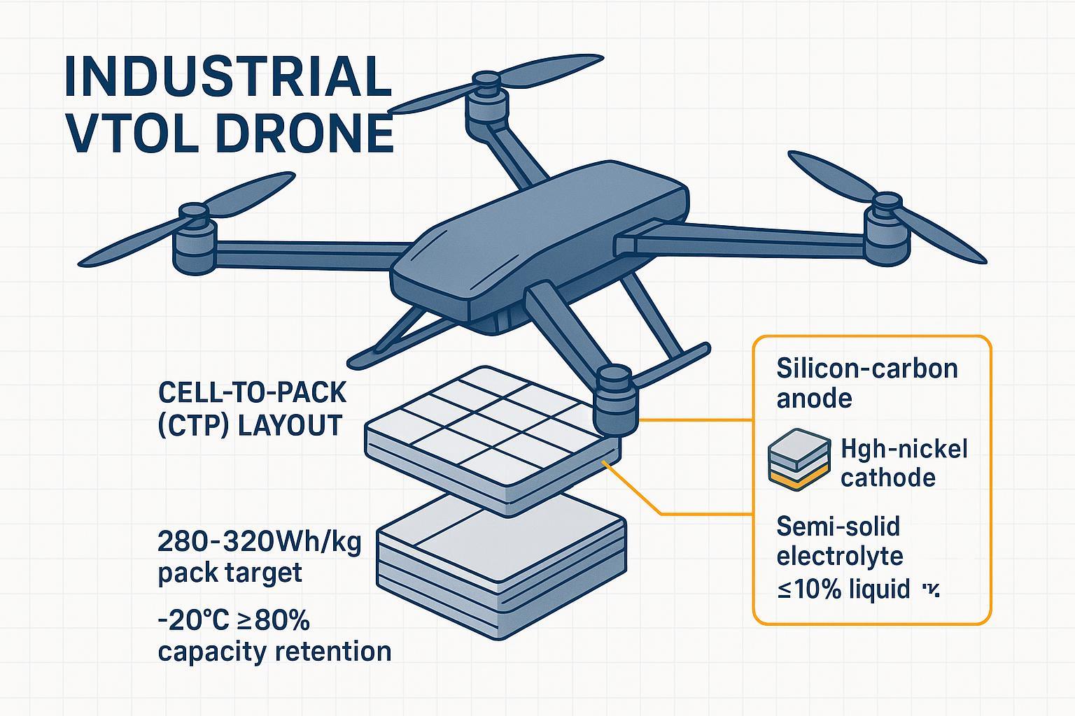
- Energy density realities: Pack‑level 180–250 Wh/kg remains a solid conservative planning band for industrial Li‑ion/LiPo. Ambitions to 300+ Wh/kg are discussed in sector white papers; aircraft‑level analysis in the advanced air mobility community typically assumes a broad 200–330 Wh/kg corridor for mature designs—see the industry association’s white paper, Demystifying AAM (v1.1), for directional ranges used in aircraft contexts (AAM white paper PDF). Treat UAV pack claims above ~250 Wh/kg as supplier‑specific and verify.
- C‑rate ranges: Many industrial endurance packs in the 6S–12S, 16–22 Ah bracket advertise continuous ratings from 15C to 30C, with short bursts higher; confirm thermal testing and connector limits.
Integration guardrails: voltage, KV, ESC, and telemetry
Voltage selection doesn’t happen in isolation. Motor KV and propeller size set the operating RPM band for a given voltage; ESCs have absolute voltage limits and thermal constraints. Before freezing your S‑count, confirm all three:
- ESC maximum voltage (Vmax) and current (Imax) under your cooling assumptions.
- Motor KV × voltage at your prop load keeps RPM within the efficient thrust window.
- Connector, wire gauge, and fusing can tolerate both continuous draw and takeoff bursts.
Telemetry closes the loop. In PX4, BatteryStatus and power‑module/BMS integrations expose voltage, current, temperature, and remaining percentage to your GCS for live margin checks; see the PX4 BatteryStatus message overview for the field semantics (PX4 docs). In DroneCAN ecosystems, dedicated BMS nodes can publish pack health to the CAN bus for the autopilot to act on.
Practical BMS example (neutral)
Some integrators use smart BMS logic to cap current at low temperatures and to log cell‑level events for root‑cause analysis. A technical explainer on how BMS thresholds and telemetry improve safety and lifespan provides additional context—see BMS role in drone battery performance for concepts like current/temperature enforcement and balancing (Herewin technical article). Use such controls to enforce the current limits you sized on paper. Smart BMS logs can also support flight incident analysis and internal compliance audits alongside the UN38.3 and CE documentation you’ll be asked for.
Compliance and logistics mini‑playbook (2026)
Transport and market access can bottleneck a program if you leave them late. Two essentials for lithium‑ion packs:
- UN38.3 testing: Before air shipment, packs must pass the eight UN38.3 tests (T.1–T.8): altitude simulation, thermal, vibration, shock, external short‑circuit, impact/crush, overcharge, and forced discharge. The list and criteria are defined in the official UN publication—see the UN Manual of Tests and Criteria, Section 38.3 (UNECE, official PDF) (UN 38.3 section PDF). Request the UN38.3 Test Summary (TS) from your supplier and verify IDs and dates match the shipped design revision.
- IATA state‑of‑charge limits (air cargo): For UN3480 lithium‑ion batteries, the 2026 guidance requires a state‑of‑charge not exceeding 30% for standard carriage, with operator and State approvals needed to exceed it under Special Provision A331. See the official IATA Lithium Battery Guidance Document (2026) for details of PI 965/966/967 and labeling/marking requirements (IATA 2026 guidance PDF).
CE and IEC notes (EU access): IEC 62133‑2 is frequently used to demonstrate cell/battery safety, but CE conformity for UAV systems depends on applicable EU directives and harmonized standards at the equipment level (e.g., LVD, EMC). Treat IEC/UL 62133‑2 as supporting safety evidence and complete a directive‑based conformity assessment with qualified SMEs.
A compact, real‑world checklist before you cut POs
- Verify endurance math with flight logs at operating temperature, not just at 25°C bench tests.
- Freeze S‑count only after confirming ESC voltage rating and motor KV/prop efficiency at that voltage.
- Size connectors, wiring, and fusing for measured peak currents, not nominal averages.
- Require a valid UN38.3 Test Summary and plan IATA ≤30% SoC shipments with correct paperwork.
- Enable BMS/telemetry alerts for voltage sag and cell temperature; test your failsafes in wind and cold.
Navigating the trade-offs between energy density, C-rate, and thermal limits is a core challenge in heavy-lift integration. To support the community, the engineering team at Herewin provides complementary propulsion-matching reviews and sizing audits. You can submit your motor KV, target payload, and flight profile for a technical feasibility check based on Herewin’s internal cell characterization data (Contact Herewin Engineering).