










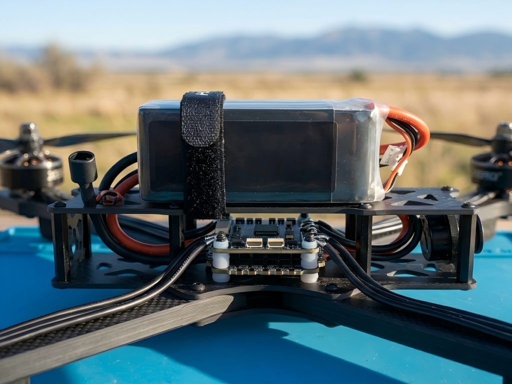
For long-range 10-inch FPV drone pilots, voltage sag is rarely a random issue. In most cases, it is the predictable result of high current draw, power transmission losses, and battery degradation stacking together under load.
The symptoms are familiar:
- sudden loss of thrust during climb or punch-out
- ESC low-voltage warnings
- unstable throttle response
- shortened usable flight time
- unexpected failsafes or forced landings
Compared with smaller 5-inch FPV builds, 10-inch long-range platforms operate under a very different electrical load profile. Larger propellers, heavier payloads, longer wiring runs, higher-capacity 6S LiPo packs, GPS modules, HD video systems, and long-duration cruising all increase continuous current demand.
And once current rises, even small resistance inside the power system starts creating meaningful voltage drop.
That is why voltage sag on 10-inch FPV platforms is usually not caused by a single bad component. It is typically the combined effect of:
- connector resistance
- wire resistance
- excessive wire length
- undersized AWG selection
- rising battery internal resistance
This guide breaks down the real electrical causes behind voltage sag and provides a practical troubleshooting workflow that FPV pilots can use to isolate the problem systematically.
What Voltage Sag Actually Means in FPV Power Systems
At the electrical level, voltage sag happens when current flows through resistance.
Every part of the power path introduces some resistance:
- battery cells
- XT60 connectors
- solder joints
- power wires
- ESC input stages
As current increases, voltage loss across those resistances increases as well.
The basic relationship is straightforward:
Voltage drop = Current × Resistance
On a high-power FPV platform, the total resistance may only be a few milliohms. But when the aircraft pulls 40A, 50A, or even 60A during aggressive throttle input, the resulting voltage loss becomes large enough to matter.
For example:
- Total circuit resistance: 0.05Ω
- Current draw: 40A
Result:
40A × 0.05Ω = 2V voltage drop
On a 6S LiPo system, that is significant.
A fully charged 6S pack starts around 25.2V. Many ESC low-voltage protections begin triggering near 21V. Losing 2V under load can push the system into instability even when the battery still has usable capacity remaining.
That is why pilots often see:
- sudden throttle collapse
- voltage warnings under punch-out
- recovery after throttle reduction
The battery is not necessarily “empty.”
The system simply cannot maintain stable voltage under load anymore.
Why 10-Inch FPV Platforms Experience More Voltage Sag
The problem becomes much more common on 10-inch long-range drones because the entire platform is designed around higher sustained power demand.
Several factors compound together.
Higher Continuous Current Draw
Large propellers require significantly more torque.
Many 10-inch builds use motors and ESC combinations capable of:
- 1000–1500W power levels
- 30–60A burst current
- sustained cruising loads far above smaller freestyle builds
As current rises, even tiny increases in resistance produce larger voltage drop.
That is why a setup that works perfectly on a 5-inch quad may become unstable on a 10-inch platform.
Longer Power Wiring
Long-range FPV drones typically carry larger batteries mounted farther from the ESC stack.
That increases wire length throughout the power system.
And wire resistance increases directly with conductor length.
In real builds, the actual wiring path is usually much longer than the straight-line distance because wires must route around:
- frame arms
- GPS modules
- flight stacks
- camera mounts
- antenna layouts
A wire run that looks like 0.5m on the bench may easily become 0.7m or more in practice.
That added resistance becomes noticeable under high current.
More Electrical Loads Across the System
Long-range platforms rarely power propulsion alone.
Additional onboard systems often include:
- HD video transmitters
- GPS modules
- telemetry radios
- action cameras
- LED systems
- onboard computing modules
All of these increase total system current draw and raise the overall electrical load on the battery.
XT60 Connectors: One of the Most Overlooked Voltage Sag Sources
XT60 connectors are widely trusted in FPV builds, but under high current they can become a hidden resistance bottleneck.
A quality XT60 connector usually maintains very low contact resistance.
But over time, several issues increase resistance dramatically:
- worn spring tension
- oxidation on contact surfaces
- poor soldering
- low-quality connector materials
- heat damage from repeated current spikes
As resistance rises, the connector starts generating additional heat during flight.
And that creates a feedback loop:
higher resistance → more heat → even higher resistance
This is why some pilots experience worsening voltage sag over time even though nothing “looks broken.”
Frequent plugging and unplugging also wears the connector mechanically. After enough cycles, the contact pressure inside the XT60 weakens, reducing electrical contact quality.
Even a connector that still feels usable may already be introducing excessive resistance under load.
Why Wire Length and AWG Selection Matter More on Long-Range Builds
Wire resistance becomes increasingly important as current rises.
For 10-inch FPV systems, AWG selection should be treated as part of power-system design, not just cable management.
In general:
- smaller AWG number = thicker wire
- thicker wire = lower resistance
- lower resistance = less voltage drop
For high-current 6S long-range builds, common recommendations are:
| Application | Recommended Wire Size |
|---|---|
| Battery to ESC main leads | 12AWG–14AWG |
| ESC to motor wires | 14AWG–16AWG |
Using undersized wire may work during low throttle cruising, but aggressive throttle input exposes the weakness quickly.
For example, 16AWG wire may become problematic on long main battery leads carrying 40A+ loads continuously.
Voltage Drop Comparison: Common FPV Wire Sizes
The table below shows approximate voltage drop values for 1-meter copper wire runs under typical FPV current loads.
| AWG | Approx Resistance (1m) | Voltage Drop @20A | Voltage Drop @40A |
|---|---|---|---|
| 12AWG | ~0.0052Ω | ~0.10V | ~0.21V |
| 14AWG | ~0.0083Ω | ~0.17V | ~0.33V |
| 16AWG | ~0.0131Ω | ~0.26V | ~0.52V |
| 18AWG | ~0.0169Ω | ~0.34V | ~0.68V |
Under heavy load, the difference between 14AWG and 16AWG becomes meaningful very quickly.
That is why many unstable long-range builds improve immediately after shortening battery leads or upgrading wire gauge.
Battery Internal Resistance: The Hidden Cause of Severe Voltage Sag
Internal resistance is one of the most important battery health indicators in FPV systems.
And it becomes especially critical on heavy-load platforms.
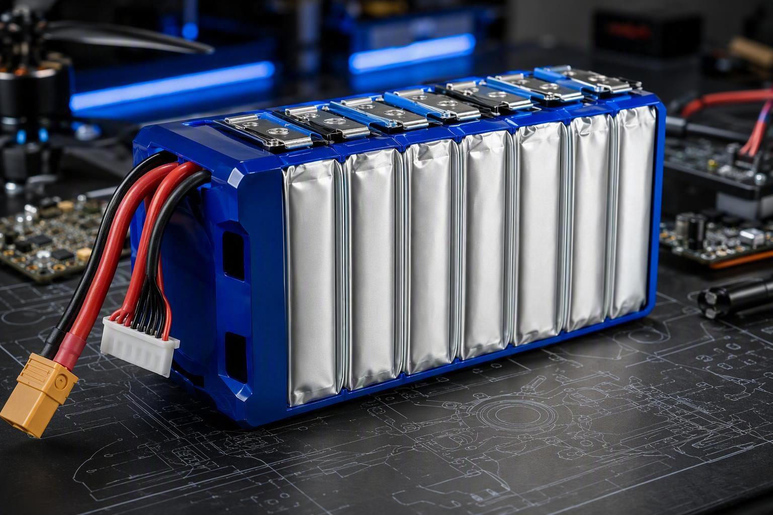
A fresh 6S LiPo pack may have:
- 2–3mΩ internal resistance per cell
But as the battery ages, internal resistance rises due to:
- repeated high-current discharge
- heat exposure
- overcharging
- deep discharge cycles
- long-term full-charge storage
Once internal resistance rises too far, voltage collapses rapidly during throttle spikes.
For example:
- Pack internal resistance: 30mΩ
- Current draw: 40A
Voltage loss inside the battery alone becomes:
40A × 0.03Ω = 1.2V
And that occurs before adding losses from wires and connectors.
This is why older LiPo packs often appear “fine” at rest but become unstable immediately under aggressive throttle.
A Practical Voltage Sag Troubleshooting Workflow
The fastest way to diagnose voltage sag is to work from the outside inward.
Start With the XT60 Connector
Check for:
- discoloration
- melting
- blackened contacts
- weak insertion force
- loose solder joints
If possible, measure connector resistance using a milliohm-capable meter.
In high-current FPV systems, replacing questionable XT60 connectors is often cheaper and faster than trying to repair them.
Evaluate Wire Length and AWG
Measure actual wire routing length, not straight-line distance.
Pay particular attention to:
- battery-to-ESC leads
- unnecessary wiring loops
- thin wire sections hidden under heat shrink
If your build uses:
- long battery leads
- 16AWG main power wire
- extended capacitor wiring
then voltage sag risk increases substantially.
Check Battery Internal Resistance
Use a proper LiPo internal resistance tester whenever possible.
As a general field reference:
| Battery Condition | Typical Internal Resistance |
|---|---|
| Healthy 6S pack | ~12–18mΩ total |
| Aging pack | ~20–30mΩ total |
| High sag / unreliable | 30mΩ+ total |
Large imbalance between cells is also a warning sign.
Even one weak cell can destabilize the entire pack under load.
Real-World Example: Diagnosing Voltage Sag on a 10-Inch Long-Range Build
A pilot experienced repeated low-voltage warnings during climb-outs on a 10-inch FPV platform using:
- 1600KV motors
- 80A ESC
- 6S 4000mAh LiPo
The battery still showed over 21V after landing, suggesting the issue was not simple battery depletion.
Inspection revealed:
- XT60 resistance slightly elevated
- 1.3m battery lead length
- undersized 16AWG main power wiring
- battery internal resistance above 30mΩ
The fix included:
- replacing the battery
- upgrading to 14AWG wire
- shortening power leads to ~1m
- installing a new XT60 connector
After the changes, voltage stability improved significantly and low-voltage events disappeared.
How to Reduce Voltage Sag on Long-Range FPV Builds
Voltage sag can never be eliminated entirely on high-power platforms.
But it can be controlled.
The most effective strategies are:
- use high-quality XT60 connectors
- minimize battery lead length
- avoid undersized power wire
- monitor battery internal resistance regularly
- avoid overheating LiPo packs
- avoid storing batteries fully charged long-term
- replace aging packs before resistance rises too far
For serious long-range FPV platforms, power-system reliability matters just as much as motors, tuning, or flight controllers.
Because once voltage becomes unstable, the entire aircraft becomes unstable.



 Español
  English
  한국어
한국어  Deutsch
  Français
  日本語
日本語  Русский
  Bahasa Indonesia
  ไทย
ไทย  العربية
  Português do Brasil
  Italiano
  Nederlands