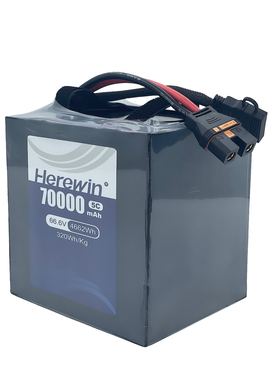




A pack marked 48 V and “lithium-ion” tells you almost nothing about whether it belongs on a particular robot. Put that pack in a warehouse AMR that runs a steady route and tops up between tasks, and what counts is energy per operating hour and how it ages over hundreds of shifts. Put the same pack in a bipedal platform whose joints pull repeated high-current pulses during balance recovery, and the questions flip: how many grams it adds, and whether the bus voltage holds through a step recovery.
This comparison cannot be settled by ranking energy density alone. A robot battery is sized against a load profile, and the same pack that gives a slow AMR a comfortable eight-hour shift can be marginal on a machine that pulls short bursts several times its average draw.
This article examines the trade-offs that matter at selection time and shows how to turn a robot’s operating profile into a shortlist for testing.
Why Battery Selection Depends on the Robot’s Operating Profile
Energy Capacity Is Only One Part of the Requirement
A pack’s nominal energy rating provides a starting point for estimating runtime, but usable energy can be lower under high loads or at temperature extremes. Cold conditions, high discharge rates, and the required cutoff voltage can all reduce the energy available to the robot. Runtime therefore needs to be estimated from usable energy under the expected operating conditions and the robot’s actual power demand.
Runtime is rarely the requirement that decides anything on its own. A pack can comfortably cover the duty cycle and still fail, because at peak current the voltage drops below the drive’s minimum operating limit and torque or speed control degrades. Every platform has that floor, and the pack has to stay above it during the worst burst, not the average one.
Mass and volume are the next constraint, since both come straight out of payload and electronics. Charging matters in two directions: the energy needed between charging opportunities determines the required usable capacity, while the charging window, charger power, and the cell’s permitted charge rate determine how much energy can be replenished before the next task. Finally, there is the service life the application can tolerate — how much capacity loss is acceptable before a pack has to come out.
Duty Cycle Changes the Selection Priorities
Take a warehouse AMR as the first case. It works long shifts of repetitive motion and docks at a charger often, so the pack may see many partial top-ups instead of one full cycle a day. What drives its economics is not energy per charge but how much charge it accepts while docked, how far it degrades over the fleet’s real duty cycle, and what pack replacement costs in maintenance and downtime.
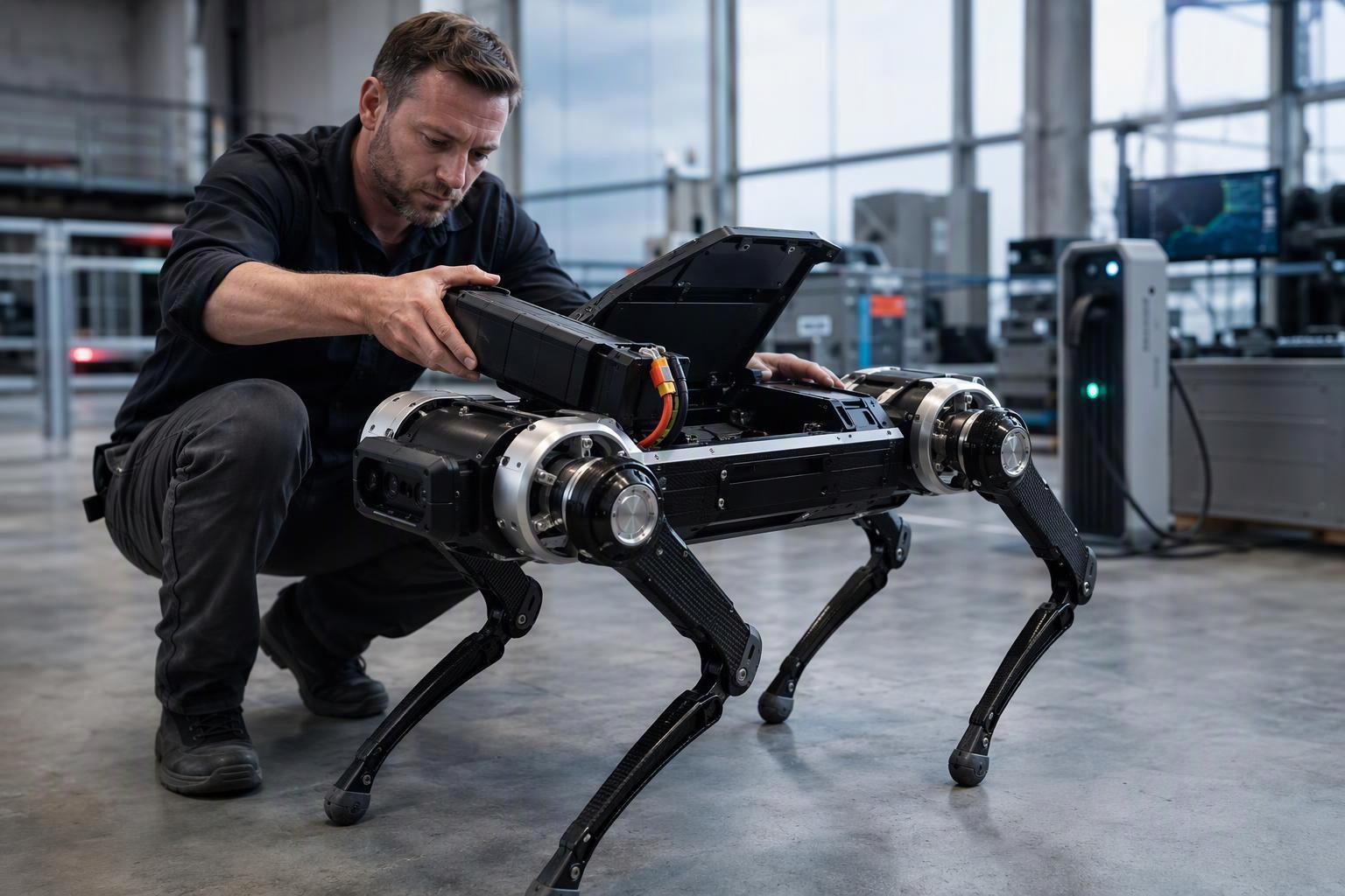
A legged robot pulls in a different direction. Its joints keep drawing short, uneven power peaks for balance and locomotion, and every kilogram carried in the torso raises the energy needed to move and ripples through the design of the limbs. On a platform like that, peak power delivery, heat rejection, and mass set the terms.
The packs look similar on paper, yet the priorities behind them diverge sharply. Which is why the duty cycle, not the category, has to come first.
Understanding the Three Battery Options
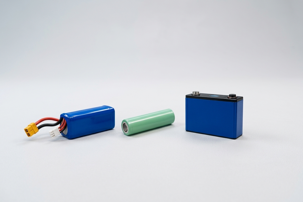
Before comparing them, one classification point is worth settling: LiPo, NMC/NCA, and LiFePO4 don’t sit at the same level. In commercial use, “LiPo” usually means a pouch-format lithium-ion cell sealed in flexible laminated foil, but the naming isn’t standardized — pouch cells are commonly labelled “lithium polymer” even though their electrodes, separator, and liquid electrolyte are often much like those in cylindrical or prismatic cans. NMC, NCA, and LFP, by contrast, name the cathode chemistry. The two sit on different axes: a pouch cell sold as LiPo may carry an NMC, NCA, or LFP cathode, and format and chemistry are independent choices.
This article therefore compares three selection routes — pouch-format cells, NMC/NCA cells, and LFP cells — not three mutually exclusive chemistries. When a supplier’s datasheet says “LiPo,” confirm the cathode chemistry separately.
LiPo Pouch Cells: Packaging Flexibility and High-Rate Options
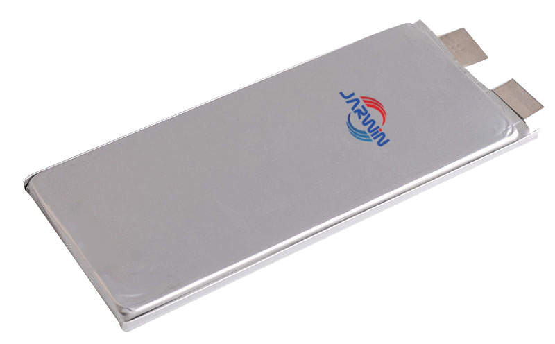
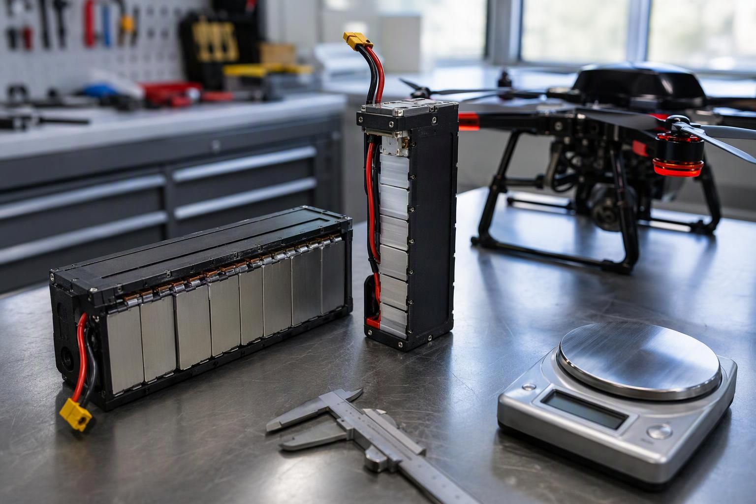
Pouch construction is worth evaluating when the battery bay is not a standard shape. Because the cell is a sealed foil envelope rather than a metal can, it can be built thin and in non-standard footprints, which lets a pack follow the internal contours of a robot instead of forcing the chassis to accommodate a cylinder or a block. Pouch cells can offer high packaging flexibility and efficient use of irregular spaces.
High-rate pouch cells exist too. Some pouch cells are designed for high-rate discharge, so this route can serve machines that need high instantaneous power. What matters is that the rating belongs to the cell design, not to the pouch format: electrode stack, tab geometry, current collection, and thermal path all do the work. A thin pouch with modest tabs will not match a high-rate design of the same footprint, however similar the two look on a spec sheet.
Pouch cells also carry mechanical obligations. They need pack-level mechanical support because the laminated foil envelope provides limited structural rigidity on its own. The enclosure and mounting scheme should follow the cell manufacturer’s compression and expansion requirements, allow for expected thickness changes over service life, and prevent movement, localized pressure, or contact with sharp edges.
Unlike a rigid metal can, the laminated envelope provides limited mechanical protection on its own. Environmental resistance and mechanical robustness depend on the cell construction and the protection provided by the assembled pack. These are design considerations, not evidence that every pouch cell is inherently less safe or shorter-lived than a rigid-format cell.
NMC/NCA Li-ion: Balancing Specific Energy and Power
NMC and NCA belong to the layered-oxide family, and they earn a look when energy and mass are both tight. Inside that family, cell makers commonly trade one against the other: a design optimized for energy may compromise power. The cathode name alone does not tell you which one you have. An energy-oriented NMC cell and a power-oriented NMC cell can differ substantially in continuous discharge rating, impedance, and heat generation, and cycle life moves with upper cutoff voltage, depth of discharge, rate, and temperature rather than being fixed by the chemistry label. Ask the supplier for continuous and pulse discharge data, impedance, and cycling results taken at conditions that resemble your load profile, then compare like with like.
Nickel-rich layered-oxide cells generally require closer attention to thermal-risk management than LFP cells. LFP generally offers better thermal stability, which can be an advantage when thermal risk is a major design consideration. Thermal behaviour still varies with cell design, state of charge, and test conditions. Chemistries diverge in how they behave — that is a design input, not a disqualifier: it defines how much thermal and electrical protection the pack needs.
LiFePO4 (LFP): Cycle Life and Thermal Stability
LFP is often attractive for two reasons that matter at selection time: many LFP cells offer long cycle life under suitable operating conditions, and the chemistry generally compares favourably on thermal stability. Both advantages depend on the specific cell and on how it is tested, so comparisons should use data collected under comparable depth of discharge, temperature, charge rate, and end-of-life criteria.
The cost is specific energy. LFP typically gives up watt-hours per kilogram against layered oxides, so the same usable energy generally needs more mass or more volume. LFP’s relatively flat discharge-voltage profile can help maintain a stable voltage over much of the discharge range, but it also makes state-of-charge estimation from voltage alone less straightforward.
Better thermal stability is not immunity. LFP cells still vent, still require a protection system, mechanical containment, and thermal design, and still fail if abused. The chemistry shifts the risk profile; it does not remove the engineering.
Comparing LiPo, NMC/NCA and LFP for Robotics
The table below consolidates the differences that matter at selection time. The three columns are a comparison of common procurement routes — a format choice and two cathode families — not a ranking of three mutually exclusive chemistries. Pouch cells are described in structural and mechanical terms because that is what the format determines; their power and thermal behaviour depend on the specific cell design and on the pack built around it.
Core trade-offs and what to check
Evaluation factor | LiPo pouch cells | NMC/NCA Li-ion | LFP Li-ion | What to verify |
|---|---|---|---|---|
Energy and mass | Set by the cell design and by how much pack-level structure the pouch format requires | Often attractive where specific energy is a priority, depending on the cell | Typically trades some specific energy for other benefits, depending on the cell | Cell Wh/kg and Wh/L at the stated C-rate, plus pack-level figures including enclosure and hardware |
Power capability | Set by the specific cell design — high-rate pouch builds exist, but the format alone does not confer it | Varies between energy-oriented and power-oriented cells | Depends on the selected cell and its power design | Continuous and pulse ratings at the intended temperature and pulse duration, with the voltage floor stated |
Cycle life | Set by the cell and its operating conditions, not by the format | Verify cell-specific data under comparable conditions | Often attractive for frequent-cycling applications, depending on the cell | End-of-life criterion, depth of discharge, rate, and temperature of the cycle test |
Thermal stability | Depends on the cathode chemistry and cell design; pouch construction adds mechanical and enclosure considerations | Requires appropriate thermal and electrical protection | Generally offers favorable thermal stability, but still requires protection | Abuse-test data for the cell, plus the pack’s thermal and electrical protection design |
Packaging | Sealed foil envelope; flexible shape, but the pack must supply structure and support | Available in multiple formats, including cylindrical, prismatic, and pouch | Commonly cylindrical or prismatic; pouch versions also exist | Cell dimensions, swelling allowance, compression requirement, and mounting scheme |
Read across the rows and the distinctions narrow quickly. An odd battery bay makes pouch formats worth evaluating. A tight mass budget makes high-specific-energy NMC/NCA cells worth evaluating. Frequent cycling, where additional mass is acceptable, makes LFP worth evaluating. Peak power does not point to any one route, because it depends on which cell in each family you shortlist. Treat the table as the first cut, not the answer.
How Battery Requirements Differ Across Robot Applications
Robot categories are a useful starting point for a shortlist, but they are not a specification. Integrators building the same class of machine often choose opposite charging strategies or work to quite different mass budgets. The scenarios below explain why each constraint set pushes the shortlist in a particular direction; Table 2 is the quick-reference version.
AGVs and AMRs: Charging Strategy and Lifecycle Cost
A warehouse mobile robot’s battery decision is driven less by single-charge runtime than by the charging plan and the cost of running the fleet for years. Long operating hours and frequent top-ups make cycle life and charge acceptance matter more, and a few extra kilograms in the chassis matter less.
Opportunity charging is a common place for fleet estimates to go wrong. A short top-up is not a full cycle, and plug-ins per day do not convert into cycle count. What ages the pack is energy throughput, the depth of each partial cycle, temperature in and out of charge, and the hours spent sitting at high state of charge. Estimating service life from charge frequency alone can be misleading. You need the real throughput figure and cell aging data taken at conditions close to yours.
Humanoid and Legged Robots: Power, Mass and Thermal Limits
For a bipedal or legged platform, the battery has to solve two problems at once. Joint actuation and balance control produce repeated power peaks, and the pack’s mass feeds directly back into the energy needed to move and into the mechanical design of the torso.
In a tightly mass-constrained design, added battery mass can also increase the loads on actuators and structural components, creating further trade-offs in the overall robot design. The effect depends on the robot’s mechanical architecture and control strategy, but it is one reason to evaluate battery mass at the system level rather than in isolation.
The choice between a high-power NMC/NCA cell and a high-rate pouch comes down to the format that fits the torso, the bus voltage, and the measured pulse capability. LFP shouldn’t be excluded on chemistry grounds alone. A heavier pack that meets the pulse requirement may still cost too much locomotion energy, and a lighter pack that drops below the drive’s minimum voltage under peak load fails regardless of its mass.
Small Biomimetic Robots and Compact Platforms: Weight and Packaging
On a small platform, the pack can be a large share of total mass, which turns mass and packaging from secondary concerns into the first ones you spec. These machines still pull burst current, and pulse capability plus temperature rise have to be measured, not inferred. Rapid prototype iteration does not remove the need to validate pulse capability and temperature rise under representative operating conditions.
Inspection Robots and Collaborative Systems: Safety and Operating Requirements
Inspection robots and collaborative arms vary too widely for a category-level rule. A robot that patrols continuously has almost nothing in common with one that works a fixed station at modest power draw. Human proximity raises the bar on containment, protection, fault behavior, and thermal management, but it doesn’t by itself dictate LFP — the operating environment, load, charging method, and safety architecture decide that.
Application scenarios and selection logic
Robot application | Key constraints | Candidate options to evaluate | What to verify |
|---|---|---|---|
AGV/AMR | Charging schedule, lifecycle cost, runtime, available space | LFP or NMC/NCA, depending on the duty cycle | Energy throughput per day, partial-cycle aging data, charge acceptance at site temperature |
Humanoid and legged robots | Peak power, battery mass, thermal limits, packaging | High-power NMC/NCA or high-rate pouch cells | Pulse capability at the drive’s voltage floor, mass budget, temperature rise over a realistic motion cycle |
Small biomimetic robots | Mass, pulse demand, compact packaging | High-rate pouch cells or other qualified lightweight options | Pulse current and temperature rise, swelling allowance, mechanical retention |
Inspection robots and collaborative systems | Operating environment, safety requirements, runtime, maintenance | LFP or other systems that meet the application requirements | Fault behavior, containment, thermal design, maintenance interval |
These are not standardized battery choices, and the candidate column is a set of screening directions rather than a recommendation by robot category. Robot categories indicate which constraints may become important first, but the actual load profile, mass budget, charging strategy, and safety requirements determine which options are worth evaluating.
A Practical Framework for Selecting a Robot Battery
Once two or three candidate cells have been shortlisted, the next step is to define the pack requirements and the tests needed to validate them. The four steps below cover what has to be specified before hardware is ordered.
Define the Load Profile
Start with measurements or realistic estimates of:
Continuous and peak current, including the duration of each peak and how often it repeats.
Required runtime between charge opportunities, converted into usable energy at the expected discharge rate.
The minimum permitted voltage at the drive, which sets the sag limit the pack must respect at peak current.
The operating temperature range, including cold starts and any hot enclosure conditions.
Also check the selected cell’s nominal voltage and permitted charge-voltage range when defining the series configuration. The number of cells in series must keep the pack’s voltage within the drive’s operating range across the permitted states of charge, while accounting for voltage drop under load and the charger’s required cutoff voltage.
A pack that falls below the drive’s minimum voltage at peak load does not meet the requirement, and increasing nominal capacity alone is not a reliable fix unless the revised design also meets the voltage and current limits.
Set Mass and Packaging Limits
Compare complete packs, not cells. The relevant figures are:
Total pack mass and volume, including enclosure, busbars, connectors, and mounting hardware.
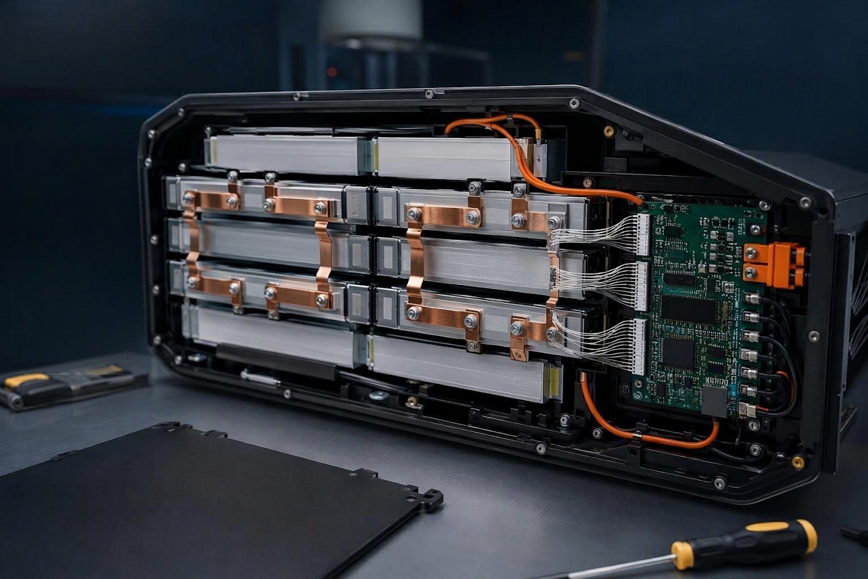
The protection electronics, interconnection, structural support, and thermal management the chosen format requires — a pouch pack may require more explicit structural support and expansion allowance, depending on the cell design.
The battery bay geometry and the mechanical retention scheme, including how the pack is restrained under shock and vibration.
A cell-level Wh/kg advantage does not necessarily translate into the same advantage at pack level, because enclosure, interconnection, structural support, and thermal management add different amounts of mass to different designs.
Evaluate Charging and Lifecycle Requirements
The charging plan and the expected service life together determine what the pack has to deliver over time. The following items should be settled before the cell choice is fixed:
Daily operating time and the available charging windows, including their duration and frequency.
The charge rate the cell will accept, alongside the power the charging infrastructure can deliver — a fast charger doesn’t make a cell charge faster than its own limit.
Permitted charge current and the temperature conditions during charging.
Expected cycle life and the end-of-life criterion the fleet will actually use — a capacity threshold, an impedance threshold, or a runtime threshold.
Maintenance, replacement, and downtime cost, which often dominates the cell price difference over a fleet’s service life.
There is no universal percentage of discharge time or battery-to-vehicle mass ratio that decides the chemistry. Those thresholds appear in informal guidance, but they are not derived from test data and should not be used as selection rules. The decision inputs are the measured load profile, the pack-level mass and volume, and the aging data at the application’s conditions.
Validate the Candidate Pack
Before committing, confirm on hardware:
Voltage response under the real load profile, including the worst-case peak and the lowest temperature.
Temperature rise at peak and continuous load, measured at the cell and at the pack surface.
Charging behavior and protection settings, including taper, cutoff, and fault response.
Mechanical retention and environmental robustness — vibration, shock, humidity, and the swelling allowance over life.
Cycle life and capacity fade under a duty cycle that resembles the application, not a standard constant-current test.
Cell-level data and pack-level testing aren’t interchangeable, and however complete a datasheet looks, it says nothing definitive about how an assembled pack will behave.
Choose the Battery for the Duty Cycle, Not the Label
The pack’s label is a weak guide on its own; what the robot actually draws matters more. Pouch formats are worth evaluating where the bay is an awkward shape. NMC/NCA is worth evaluating when specific energy is the binding constraint. LFP is worth evaluating for frequent-cycling applications where thermal stability is a key consideration. Each of those is a starting direction, and the only way to close it out is to run the candidate pack through the profile you actually measured.
If you’re weighing battery options for a robotic platform, Herewin’s battery engineering team can review cell options against your voltage, load profile, packaging constraints, and lifecycle requirements.


 Español
 English
 한국어
 Deutsch
 Français
 日本語
 Русский
 Bahasa Indonesia
 ไทย
 العربية
 Português do Brasil
 Italiano
 Nederlands