


Fast charging at 2C–3C can be both safe and ROI‑positive for industrial drone fleets—if you enforce the electrochemical window and let the BMS lead. This guide packages the practical standards context, charger selection criteria, audit‑ready SOPs, risk controls, and a simple ROI model you can reuse across projects.
What fast charging means in 2026 and why the electrochemical window matters
Fast charging refers to sustained 2C–3C charge rates on 12S–14S lithium packs typical of multi‑rotor industrial fleets. The value is obvious: shorter turnarounds, more missions per day, and higher asset utilization. The catch is interface stability. At high currents, Joule heat accelerates side reactions, the SEI can degrade, and lithium plating risk grows as pack temperature and SOC rise. Think of the electrochemical window like lane markers on a highway: stay centered with temperature and voltage, and traffic flows; drift too far, and you invite collisions.
Standards give us boundaries. The UN overcharge abuse test runs packs at twice the manufacturer’s maximum charge current for 24 hours to define a destructive edge case; it’s a safety boundary, not an operating target, as shown in the official UN38.3 manual T.7 overcharge description. Protective features and high‑rate charge evaluations embedded in mobility battery standards (summarized for Edition 3 in Intertek’s notice on UL 2271 updates) reinforce why temperature locks, fault handling, and current limits must be enforced by design—not by operator “feel.”
That’s why any credible program for industrial drone battery fast charging starts by defining a safe temperature band, a mid‑SOC window, and a taper schedule that reduces current as you approach the top of charge. The BMS should negotiate those limits in real time so the charger never guesses.
Charger and infrastructure selection beyond wattage with BMS sync
The single most important criterion is the “digital handshake.” Your charger must read and respect BMS‑published limits like MaxChargeCurrent, MaxChargeVoltage, pack and cell temperatures, charge‑inhibit flags, and SoC/SoH. For protocol baselines and message concepts, see the UAV data type references in UAVCAN’s public list of data types and implementation guidance available from semiconductor vendors such as Texas Instruments’ battery management portal. In practice, integrators commonly mix CAN or CAN‑FD for high‑rate data with SMBus or UART for legacy packs; the key is that limits flow from the pack, not the charger’s static presets.
On hardware scale, a 3 kW‑class, dual or multi‑channel unit is a practical floor for fleets running parallel turnarounds. Verify continuous per‑channel current at 12S–14S, not just peak watts. Ruggedized mobile carts should handle generator or inverter input without browning out, provide forced‑air cooling or ducted heat extraction, and meet ingress and corrosion protection suitable for field work. Safety bodies emphasize NRTL‑listed equipment, hazard communication, and proper wiring; review OSHA’s lithium battery safety bulletin and NFPA’s committee documentation summarizing ESS spacing and ventilation principles in NFPA 855 materials when designing high‑power mobile charging carts.
For a practical market scan and to structure your checklist, you can review the charger category overview on Herewin drone battery chargers and then confirm the specifics below with vendors.
- Required BMS handshake signals: limits, temperatures, inhibit flags; derate on request.
- 3000 W or higher power with stated per‑channel continuous current at 12S–14S.
- Power quality and EMC tolerance for generator or inverter inputs with surge protection.
2026 drone fast charging SOPs you can audit
A good SOP keeps you inside the electrochemical window while giving technicians clear go/no‑go gates and automatic fallbacks.
Use the table below as a fast, auditable decision layer on top of your charger’s closed‑loop control. If there’s any conflict, the pack datasheet and the BMS‑published limits win.
| Condition to check
(before and during charge) |
Compliance Criteria | Mitigation / Fallback | What to record |
|---|---|---|---|
| Ambient/pack temperature is within the published fast‑charge band (General recommended charging environment is 10–35°C, and many packs operate from −20 to 60°C; fast‑charge limits are pack‑specific) | Allow >1C only when the BMS reports “charge allowed” and temperatures are stable | Fall back to ≤1C or stop charge; cool/heat soak until stable; quarantine if the pack can’t stabilize | Start/end temps, peak temp, time‑to‑stabilize, any temperature derates |
| Cell max voltage headroom (cell max voltage is comfortably below the BMS max‑charge voltage limit) | Continue CC phase; begin taper earlier if nearing the top of charge | Initiate taper/derate immediately; if a cell hits the limit, stop and balance/diagnose | Max cell voltage, time at high voltage, SOC at taper start |
| Cell delta‑V (cell‑to‑cell dispersion) stays below your fleet redline | Permit fast charge in the mid‑SOC window; keep monitoring dispersion trend | Drop to ≤1C; schedule a diagnostic cycle if dispersion persists or grows | Delta‑V at start, peak delta‑V, trend over session |
| BMS communications are stable (CAN/SMBus/UART telemetry updates on time; no repeated reconnects) | Trust real‑time protections (derate, inhibit flags) and proceed | Treat as a safety fault: pause charge, re‑establish link, and do not resume >1C until telemetry is live | Packet loss/retries, reconnect count, longest telemetry “freeze,” timestamped fault logs |
| BMS status is clean (no active faults; MaxChargeCurrent/MaxChargeVoltage are being read and respected) | Proceed; charger follows BMS limits in real time | Stop charge, isolate the pack, and open a service ticket | Fault codes, limit values read, charger setpoints vs. BMS limits |
| Post‑charge recovery hold (thermal equalization and balancing settle) | Hold ~10 minutes (or per pack spec) before redeploying | If temps remain elevated or delta‑V stays high, extend hold and schedule inspection | Hold duration, delta‑T during hold, delta‑V after hold |
| Audit log completeness (session metadata captured end‑to‑end) | Close session; release pack to rotation | Keep pack out of rotation until a logged, compliant session is completed | Pack ID, charger ID, operator, start/end SOC, kWh in, derates, anomalies |
For a deeper walkthrough of operational staging and technician checklists, see the training‑focused guide on durable lithium battery SOPs for drone programs and adapt it to high‑rate scenarios with BMS‑synchronized tapering. If you publish internal Herewin fast‑charge telemetry later, you can tighten the temperature and dispersion gates to match your validated window.
Risk mitigation and failure precursor detection
Thermal runaway is not a single event but a chain: localized heating, exothermic reactions, gas generation, pressure rise, and then propagation. Abuse and protection concepts in mobility standards (summarized by Intertek’s notice on UL 2271 Edition 3 scope changes) and installation best practices in NFPA 855 committee documentation justify why fleets should rely on automated protections, not operator intuition. What should your technicians actually watch for during industrial drone battery fast charging?
- Rapid rise in pack or cell internal resistance across cycles or within a single session
- Expanding cell voltage dispersion during charge or under load and persistent hot spots across the pack
- Gas or pressure sensor activity where available, and any recurring temperature non‑uniformity beyond normal patterns
- Unstable BMS communications: frequent packet loss, repeated reconnects, or “frozen” telemetry over CAN/SMBus can hide real‑time cell stress and let the pack drift outside the electrochemical window
When any precursor appears, drop to ≤1C, isolate suspect packs, and schedule a diagnostic cycle with extended logging.
ROI worked example for fast charging in fleet operations
The business case rises or falls on two numbers—the extra missions you can fly per day and the cycle‑life penalty you accept at 2C–3C relative to 1C. Use a transparent, parameterized model so finance and operations can adjust assumptions together. The cost‑stacking logic follows methodologies used in NREL’s technology baselines for battery systems; see the structure of the NREL ATB for utility‑scale storage for how capex, O&M, and augmentation are treated.
Note: While 2C-3C is standard for high-density NMC packs, LiFePO4-based systems should prioritize a 1.5C-2C ceiling unless specifically rated for ultra-fast charging to avoid early SEI degradation.
Assumptions for a hypothetical multi‑rotor fleet segment:
- Baseline: 6 missions/day at 1C charging; fast charge enables 8–9 missions/day.
- Cycle‑life penalty at 2C–3C vs 1C: −10% to −30% equivalent full cycles to 80% SoH (range; determine via your telemetry and vendor data).
- Pack replacement cost and O&M: use your procurement data; allocate overhead similar to ATB structures.
Sensitivity snapshot (illustrative math; replace with your numbers):
| Utilization uplift vs 1C | Cycle‑life penalty −10% | Cycle‑life penalty −20% | Cycle‑life penalty −30% |
|---|---|---|---|
| +15% missions/day | Positive ROI in year 1 if pack cost share ≤ 18% of revenue per mission | Break‑even by month 16–20 | Likely negative without operational efficiencies |
| +25% missions/day | Positive ROI in year 1 with pack cost share ≤ 25% | Positive ROI by month 12–15 | Break‑even by month 18–24 |
| +40% missions/day | Strong ROI; consider adding charging carts to remove queue time | Positive ROI in year 1 | Positive ROI if failure rate stays within warranty bands |
How to apply it: quantify mission revenue or value per sortie, estimate fast‑charge energy and generator fuel costs where relevant, then stress‑test results against higher‑than‑expected failure rates. If you want a second lens for utilization economics in storage and mobility contexts, McKinsey’s public work offers framing you can adapt to drone operations; align it with your own telemetry and finance models.
Technology outlook for the next 12 to 24 months
- AI‑adaptive charging: Real‑time impedance and SoH feedback can steer current profiles to avoid plating while holding higher average C‑rates. Expect controller updates that optimize by pack, by day, even by session, rather than one static CC‑CV curve. Rollout should start in lab‑validated profiles for selected fleets before wide adoption.
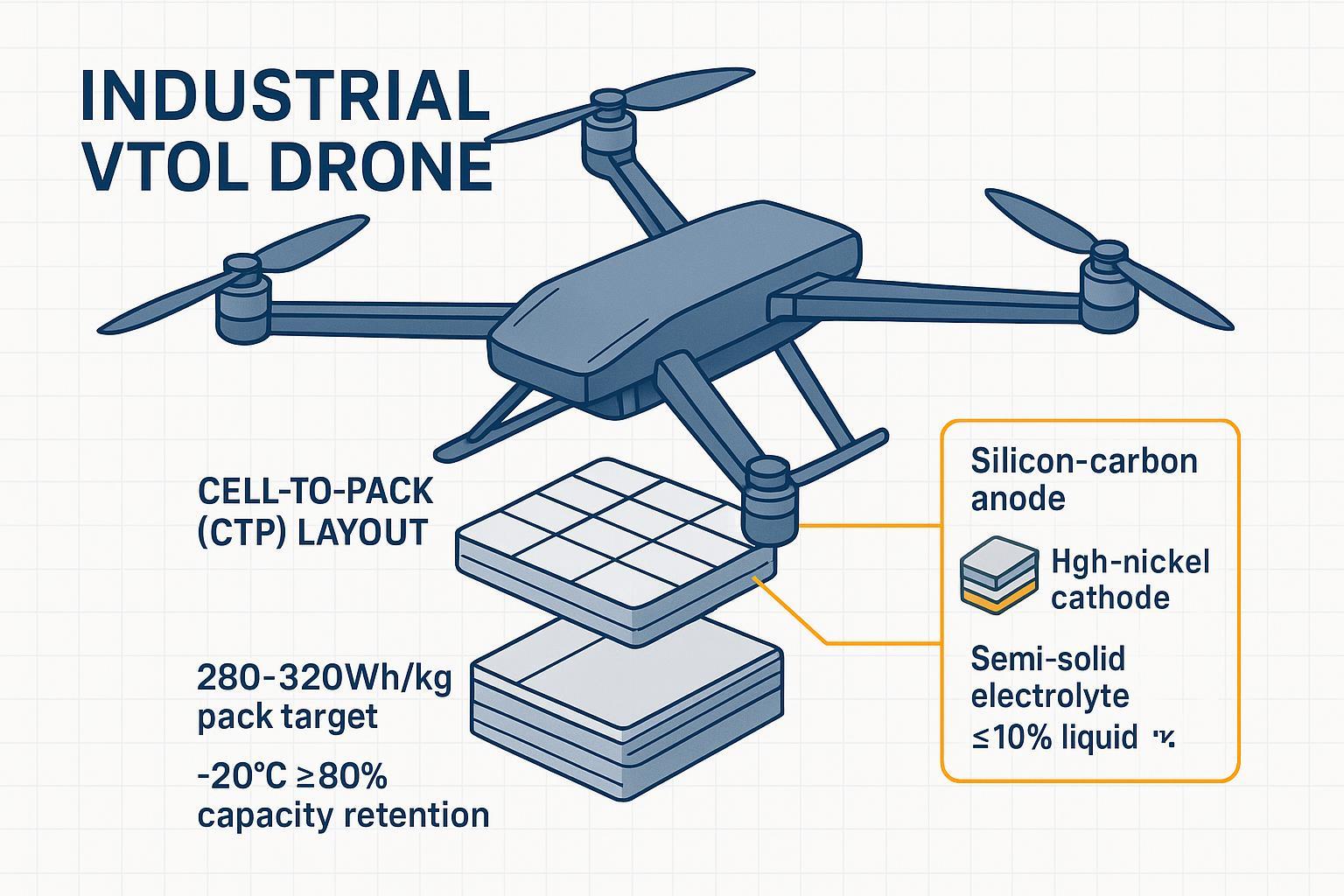
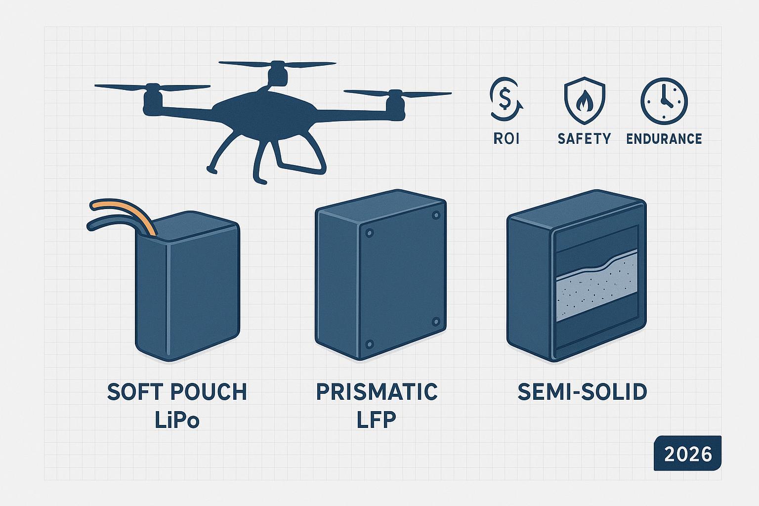
- Semi‑solid state transition: Partial solid electrolytes that retain a small liquid fraction aim to improve safety margins and tolerance to abuse, which could enable more forgiving fast‑charge windows. Treat marketing claims cautiously and demand application‑level validation on your specific duty cycles.
Both trends can be planned for today, specify chargers with protocol headroom for adaptive control and keep your data pipeline clean so models can learn from real missions.
Micro‑example of a BMS‑synced 2C charge session in practice
Consider a heavy‑lift mission pack connected to a 3 kW dual‑channel ground charger. The charger reads the BMS limits at start: MaxChargeCurrent, MaxChargeVoltage, temperature, SoC, and charge‑inhibit. The session is allowed at 2C because the pack sits in the mid‑SOC window and bulk temperature is within band. Current holds near 2C through mid‑SOC, then the charger automatically tapers above the high‑70s SOC to manage overpotential. When an onboard temperature sensor trends toward the upper threshold, the charger derates by 20% per the BMS request. At end‑of‑charge, the BMS signals balance completion and the system enforces a ten‑minute recovery hold. Logs capture start/end SoC, delta‑T, any derates, and max delta‑V across cells for audit.
For context on industrial packs used in heavy‑lift and inspection scenarios, see Herewin’s battery solutions for industrial missions and map the same handshake principles to your fleet.
Next steps for a 2C–3C fast‑charge rollout
Industrial drone battery fast charging becomes predictable when you shift decisions from “charger knobs” to BMS‑synchronized limits, operate inside a defined electrochemical window, and design carts and depots with the same safety discipline you’d apply to any high‑power system. The UN38.3 overcharge boundary sets a red line you should never approach, while implementation resources like UAVCAN data types and TI’s battery management guidance help translate limits into real‑time control. Use the ROI table as your shared language between engineering and finance.
If you’re planning a 3 kW ground system or mobile cart rollout and need help validating BMS sync and SOPs, you can consult Herewin’s engineering team for integration support.