












In the rapidly expanding commercial e-mobility market—spanning urban delivery fleets, battery swapping networks, and commuter transport—operating economics depend heavily on battery pack longevity. While cell manufacturers specify nominal cycle lives exceeding 1,000 to 2,000 full charge-discharge cycles under laboratory conditions, real-world fleet operators frequently encounter severe capacity fade, premature range reduction, and elevated warranty replacement costs within 12 to 18 months of deployment.
For original equipment manufacturers (OEMs), battery pack distributors, fleet operators, and maintenance engineering teams, this discrepancy represents a major financial liability. Unpredictable State of Health (SOH) degradation erodes total cost of ownership (TCO) models, destabilizes fleet availability, and increases capital expenditure reserves. Understanding the electrochemical root causes of premature aging—and establishing pragmatic lifecycle SOPs across daily charging, storage, thermal control, and BMS governance—bridges the gap between laboratory ratings and field performance.
Battery Aging Is Usually a Management Problem, Not a Cell Problem
When an electric motorcycle battery pack loses usable capacity or suffers from severe voltage sag under load, initial field diagnostics often point toward defective battery cells. However, extensive teardown audits and fleet analytics reveal a different reality: in many real-world cases, premature battery degradation is not caused by cell defects, but by improper charging habits, unoptimized storage conditions, and thermal management failures.
Lithium-ion battery degradation stems from parasitic side reactions that alter cell electrochemistry over time. In real-world operations, aging primarily manifests through three interconnected modes:
Loss of Active Lithium (LLI): Side reactions like SEI growth trap cyclable lithium ions, directly cutting into net pack capacity.
Electrode Degradation: Mechanical stress and lattice micro-cracking restrict the active surface area available for energy storage.
Impedance Buildup: Interfacial layer thickening elevates internal resistance ($R_i$), causing noticeable voltage sag and reduced acceleration under load.
While cell chemistry sets the theoretical boundary for energy density and cycle life, operational stress dictates how rapidly these degradation modes progress. High state-of-charge (SOC) exposure, deep discharge cycling, uncontrolled thermal conditions, and inadequate BMS protection dramatically accelerate LLI and impedance growth, causing industrial packs to age prematurely.
Cell manufacturing quality establishes a pack’s baseline capability, but operational management determines its actual service life. Systematic lifecycle control directly mitigates parasitic electrochemical degradation.
Daily Charging Strategy: Why Avoiding Extreme SOC Improves Battery Cycle Life
Daily charging routines represent the highest frequency stress factor experienced by electric motorcycle battery packs. Unrestricted charge-discharge patterns that repeatedly operate near extreme SOC conditions subject internal cell components to maximum mechanical and chemical strain.
SOC Range | Stress Level & Operational Impact | Primary Risks / Benefits |
|---|---|---|
0% – 20% SOC | Extreme Voltage Stress | Deep discharge risks, current collector damage, irreversible capacity loss |
20% – 80% SOC | Low-Stress Window | Optimal lifecycle, minimal interfacial side reactions, reduced mechanical strain |
80% – 100% SOC | High Chemical Potential | Interfacial decay, accelerated electrolyte oxidation, elevated SEI growth |
The Electrochemical Impact of Extreme SOC
Operating lithium-ion cells at extreme states of charge accelerates distinct degradation modes at both ends of the voltage spectrum:
High SOC Stress (>80% SOC): Storing or resting a lithium pack near 100% SOC holds the cathode at a high electrochemical potential (~4.2V/cell for NMC, ~3.65V/cell for LFP). This persistent high potential accelerates electrolyte oxidation and interfacial degradation, especially in high-voltage chemistries such as NMC.
Deep Discharge Stress (<20% SOC): Discharging cells below 20% SOC forces the anode potential to rise rapidly. Severe over-discharge can damage current collectors and create irreversible capacity loss, especially when cells are forced below manufacturer voltage limits.
The 20%–80% SOC Low-Stress Operating Range
For lithium-ion chemistries (such as Nickel Manganese Cobalt / NMC and Lithium Iron Phosphate / LFP), operating within a 20% to 80% SOC window is widely considered a low-stress operating range for lithium-ion battery systems. Restricting daily partial-cycle depth reduces structural expansion/contraction stress on electrode materials and minimizes parasitic interfacial reactions.
The table below illustrates representative cycle life characteristics across varying Depth of Discharge (DoD) windows and charge cutoff targets:
Operating Strategy | Effective SOC Window | DoD (%) | Representative Lithium Cycle Life Trend (80% SOH) | Dominant Degradation Mode |
|---|---|---|---|---|
Full Depth Cycling | 0% – 100% SOC | 100% | ~500 – 800 Cycles | Severe Lithium Loss, SEI Growth, Mechanical Micro-Cracking |
Standard Commercial | 10% – 90% SOC | 80% | ~1,000 – 1,200 Cycles | Moderate SEI Layer Growth, Gradual R_i Rise |
Optimized Fleet SOP | 20% – 80% SOC | 60% | ~1,800 – 2,500+ Cycles | Low Interfacial Side Reactions, Minimal Active Lithium Loss |
Cycle life trends reflect baseline laboratory reference conditions (25°C, 0.5C/1C rate). Actual results vary significantly based on cell chemistry, operating temperature, charging rate, and BMS configuration.
Distinguishing Lithium-Ion from Lead-Acid Electrochemistry
Engineering and maintenance teams transitioning from traditional lead-acid fleets to modern lithium platforms must recognize that these two chemistries require opposing charging regimes:
Lithium-Ion (LFP / NMC): Demonstrates excellent partial state-of-charge (pSOC) performance. Lithium packs do not suffer from memory effects and achieve maximum cycle life when kept within a moderate pSOC band, avoiding sustained 100% SOC conditions.
Lead-Acid: Prefers immediate full recharges to 100% SOC. Partial charging or prolonged operation at intermediate SOC causes lead sulfate crystals on the plates to coalesce into large, insoluble crystals—a process known as irreversible sulfation—which permanently reduces battery capacity and cold-cranking performance.
Long-Term Storage: Why Battery Rest Conditions Matter
Commercial e-mobility assets often undergo extended rest periods during seasonal demand fluctuations, inventory transit, or fleet overhaul phases. Improper storage protocols during these idle periods trigger severe calendar aging—degradation that occurs over time regardless of active cycling.
Lithium Storage at Moderate SOC (30%–60%)
To minimize calendar aging during long-term storage, lithium-ion battery packs are generally recommended to be stored around 30% to 60% SOC (corresponding to an open-circuit cell voltage of approximately 3.70V to 3.82V for NMC, or 3.25V to 3.30V for LFP, depending on cell manufacturer guidelines).
At moderate SOC, the internal cell equilibrium sits in a stable thermodynamic zone where:
The anode potential is sufficiently high to suppress lithium plating while avoiding structural destabilization.
The cathode potential remains low enough to minimize liquid electrolyte decomposition and gas evolution.
Parasitic side-reaction rates drop to their baseline minimum, curbing calendar aging in lithium-ion batteries over months of inactivity.
Storing lithium packs near 100% SOC significantly accelerates capacity loss over time compared to resting packs at ~40% SOC under identical ambient temperatures.
Conversely, storing packs at <10% SOC creates severe risks: ambient self-discharge and passive BMS standby currents can drain cell voltages below critical low-voltage protection thresholds, causing the BMS to lock out charging or causing permanent copper dissolution.
Storage Parameter | High SOC Storage (100% SOC) | Moderate SOC Storage (30%–60% SOC) |
|---|---|---|
Electrochemical Potential | High cathode potential (~4.2V/cell) | Balanced thermodynamic equilibrium |
Interfacial Stability | Rapid SEI growth & electrolyte decay | Minimum parasitic side reactions |
Internal Impedance | Elevated internal resistance buildup | Stable interfacial layers |
Calendar Lifespan | Accelerated capacity fade over time | Extended calendar & service life |
Lead-Acid Storage Requirements
Unlike lithium systems, lead-acid batteries stored at intermediate SOC suffer irreversible sulfation damage. Lead-acid storage protocols mandate a 100% full charge prior to storage, supported by periodic float recharges every 30 days.
Temperature Management: Why Heat Is the Biggest Hidden Battery Killer
Temperature is the single most influential environmental variable governing battery degradation rates. Ambient operating conditions, heat accumulation during heavy discharge, and thermal charging environments directly alter the chemical kinetics inside the battery pack.
Thermal Aging and Chemical Kinetics
The rate of parasitic chemical side reactions within a battery cell follows Arrhenius kinetics: as temperature increases, reaction rates rise exponentially. Elevated operational or ambient temperatures accelerate electrolyte breakdown, destabilize the SEI film, and increase internal resistance over time.
Exposing cells to temperatures exceeding 40°C triggers elevated thermal aging kinetics. The protective SEI layer on the graphite anode partially dissolves and continuously reforms, consuming cyclable lithium ions and releasing gaseous byproducts. This process increases internal pack pressure and thickens the resistive interfacial layer, leading to severe capacity drop and voltage sag.
Commercial fleets in high-temperature regions—such as Southeast Asia, Brazil, and the Middle East—face accelerated degradation due to tropical climate conditions. In these environments, heavy daily delivery schedules paired with immediate fast charging create “thermal stacking,” where motor heat and internal charging resistance compound, rapidly aging the battery.
Charging a lithium battery pack immediately after a high-speed or heavy-load delivery run creates “thermal stacking”—combining motor-induced discharge heat with charging resistance heat. Always enforce a mandatory 1-to-2-hour cool-down period before connecting fast chargers.
Low-Temperature Cold-Charging Risks
While elevated heat accelerates calendar and thermal aging, sub-freezing temperatures introduce a different failure mode: lithium plating.
At low temperatures (<0°C), the diffusion rate of lithium ions within the liquid electrolyte and their intercalation kinetics into the graphite anode structure slow dramatically. If a high charging current is applied under cold conditions, incoming lithium ions cannot intercalate into the anode structure fast enough. Instead, they deposit onto the anode surface as metallic lithium plating.
Metallic lithium plating causes permanent loss of cyclable lithium and can grow into sharp microscopic dendrites. Over repeated cold-charging cycles, dendrites penetrate the polymeric separator, creating internal dead shorts that escalate thermal runaway risks when the pack subsequently operates at normal temperatures.
How Smart BMS Extends Electric Motorcycle Battery Life
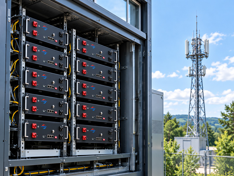
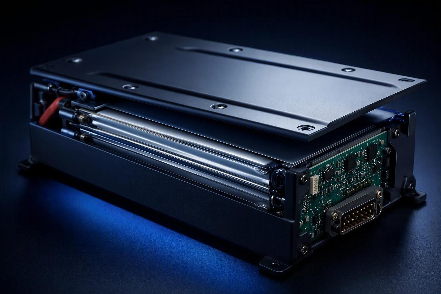
While fleet maintenance SOPs govern external handling, the internal Battery Management System (BMS) acts as the primary automated safeguard enforcing operational parameters in real time. A robust BMS architecture protects against human operational errors and maintains cell string equilibrium throughout the pack’s lifecycle.
BMS Feature Category | Key Functions & Mechanisms | Operational Objective |
|---|---|---|
Voltage Safeguards | Upper / lower voltage cutoffs, auto-disconnect logic | Prevents deep discharge & overcharge damage |
Thermal Protection | Multi-point thermistor monitoring, dynamic thermal derating | Prevents thermal runaway & interfacial degradation |
Cell Balancing | Active / passive cell string equalization | Restores full pack capacity & balances cell stress |
Telemetry & State Tracking | SOC auto-calibration, Coulomb counting, CANbus logging | Eliminates false range readings & logs fault history |
Key BMS Longevity Functions
When integrating custom lithium-ion battery pack manufacturing into electric motorcycles, the BMS firmware must be calibrated with specialized protection algorithms:
Precision Voltage Cutoffs: Hardware-level voltage monitoring prevents cells from exceeding specified upper or lower thresholds. Over-discharge cutoffs must feature automatic disconnect logic to prevent standby electronics from draining cells to zero during seasonal storage.
Dynamic Thermal Derating: Advanced BMS controllers continuously monitor multi-point thermistor inputs across cell modules. When internal pack temperatures breach predefined temperature thresholds specified by cell manufacturers and pack engineers, the BMS dynamically throttles incoming/outgoing current limits, preventing thermal runaway and mitigating heat-induced interfacial breakdown.
SOC Calibration and SOH Estimation: Extended cycling causes SOC drift in algorithms relying solely on Coulomb counting. Periodic auto-calibration at defined voltage plateaus ensures accurate SOC displays, eliminating false range calculations that lead to premature vehicle power cutoffs.
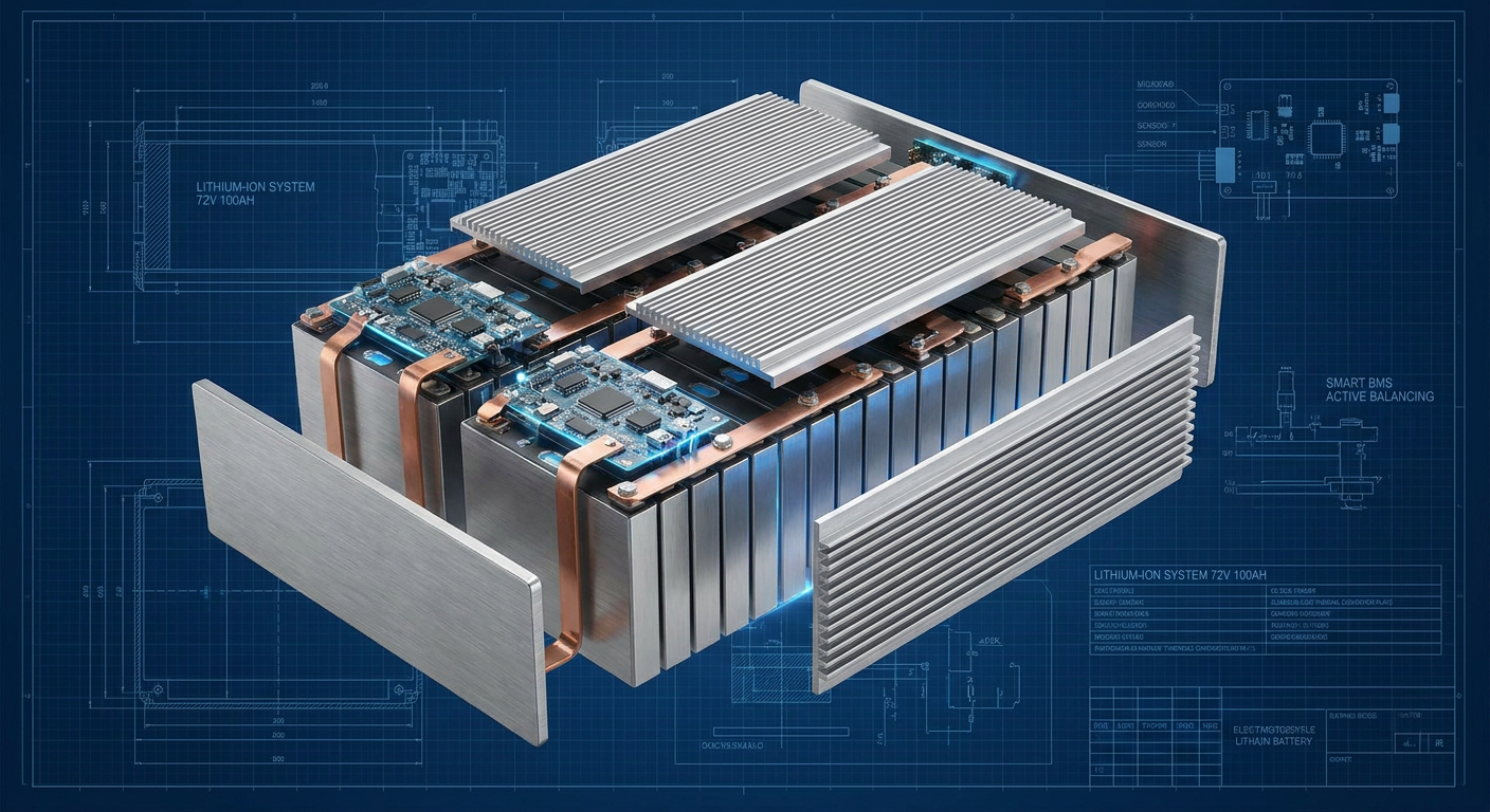
Cell String Balancing: Manufacturing variations cause slight capacity and self-discharge differences among series-connected cells over time. Without balancing, the weakest cell in a string reaches its low-voltage cutoff first, limiting the entire pack’s usable capacity. Advanced Battery Management System (BMS) architectures utilize passive or active balancing to equalize cell voltages during the final charging phase, restoring full pack capacity and preventing individual cell over-stress.
For Battery OEMs: Why Pack-Level Engineering Matters
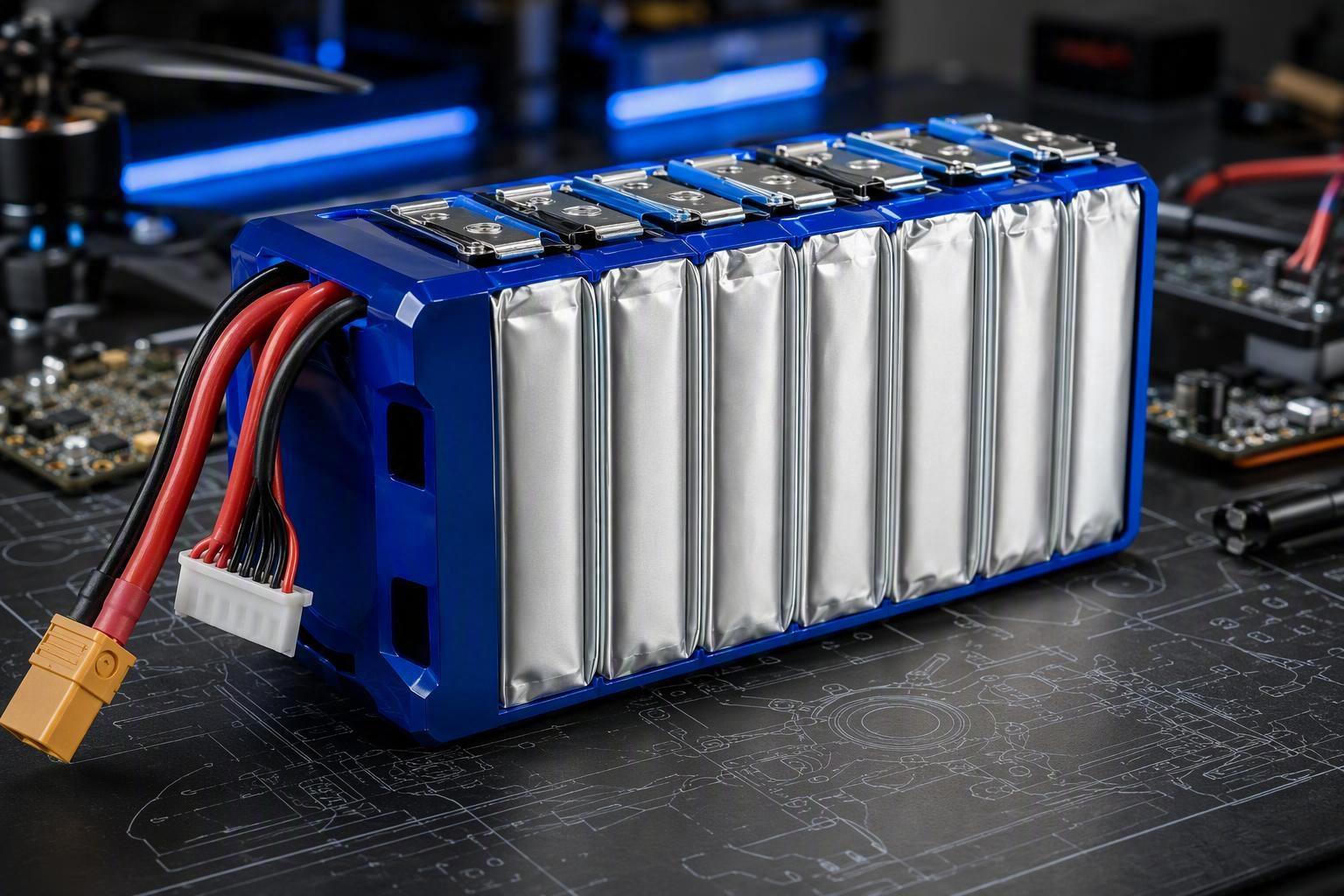
For OEM vehicle manufacturers and fleet operators, achieving maximum battery longevity depends not only on cell selection, but on full custom battery pack manufacturing. A reliable e-mobility battery system requires:
Matching Cell Chemistry: Selecting optimal cell configurations (LFP vs. NMC) or next-generation semi-solid battery technology tailored to duty cycles and ambient climates.
Calibrated BMS Tuning: Customizing protection thresholds and balancing protocols using smart BMS technology to prevent cell over-stress.
Advanced Thermal Management: Designing mechanical enclosures and heat-dissipation pathways that prevent localized hot spots across high-power e-mobility or UAV battery lifecycle applications.
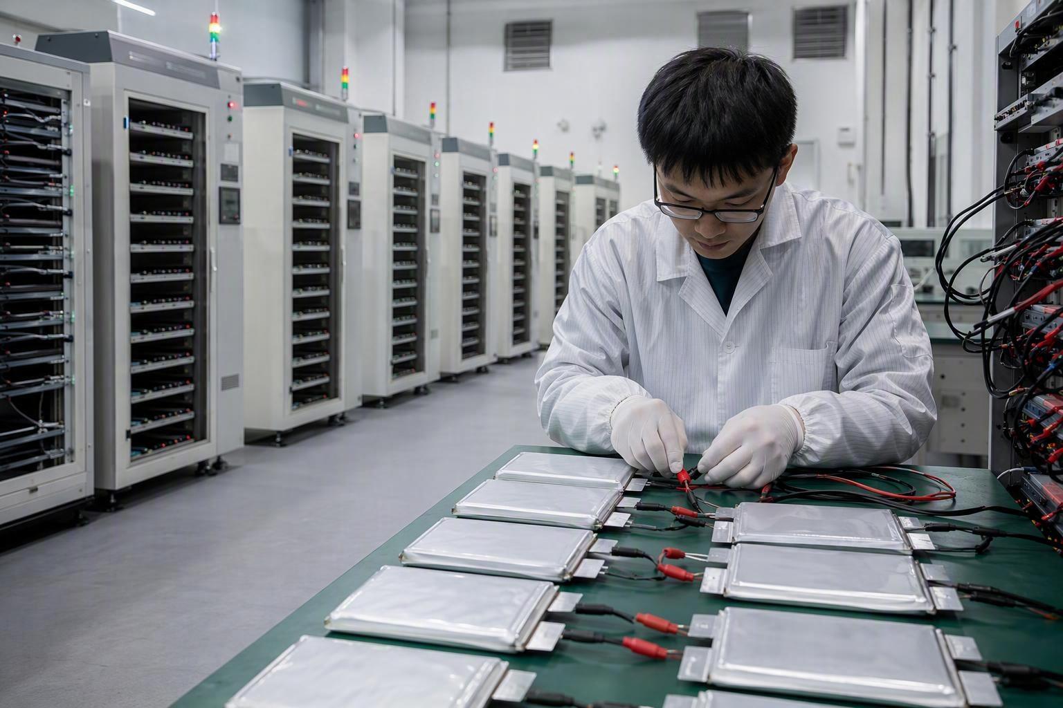
Validation Under Real Operating Conditions: Rigorous testing across vibration, temperature extremes, and rapid charge-discharge profiles.
Practical Battery Lifecycle Management Checklist
To assist e-mobility OEMs, fleet operators, and service managers in implementing standardized protocols, the following audit-friendly checklist consolidates key operational vector requirements:
Daily Fleet Operation Protocol
Enforce a daily operating window of 20% to 80% SOC for standard fleet routes.
Restrict 100% full charges exclusively to planned long-distance routes; avoid overnight high-SOC parking.
Implement a mandatory 1-hour cool-down period post-ride before initiating charging to avoid thermal stacking.
Avoid deep discharges below 15% SOC; set vehicle fleet warnings to prompt recharge at 25% SOC.
Long-Term Rest & Storage SOP
Calibrate lithium-ion battery packs to 30%–60% SOC (~3.75V/cell) prior to seasonal storage.
For lead-acid legacy units, ensure 100% full charge before rest and schedule float recharges every 30 days.
Disconnect primary pack master switches or negative terminals to eliminate vehicle standby parasitic loads.
Maintain climate-controlled storage environments within 10°C to 25°C, away from direct sunlight and rain exposure.
Perform monthly BMS telemetry checks; top-up lithium packs if self-discharge drops SOC below 30%.
BMS & Hardware Configuration
Verify BMS dynamic thermal derating parameters according to cell manufacturer and pack engineering specifications.
Configure low-temperature charge lockouts to prevent charging below 0°C without active pre-heating.
Verify active/passive cell balancing functional thresholds during scheduled fleet maintenance audits.
Audit CANbus SOH telemetry data quarterly to identify deviating cell strings before field failure occurs.
Maximizing Fleet ROI Through Systematic Battery Governance
The usable lifespan of an electric motorcycle battery pack is not determined solely by its underlying cell chemistry. Instead, it is governed by how effectively the pack is charged, stored, thermally managed, and monitored throughout its operational life.
By replacing full 0%–100% cycling with optimized 20%–80% SOC operating windows, establishing 30%–60% storage protocols, eliminating high-temperature charging stress, and specifying intelligent BMS protection, fleet managers can extend battery cycle life by 30% to 50% while mitigating field safety hazards.
Ultimately, by pairing rigorous electrochemistry with intelligent system control, commercial fleets can achieve predictable battery asset longevity and fundamentally maximize overall operational ROI.





 English
  Español
  한국어
한국어  Deutsch
  Français
  日本語
日本語  Русский
  Bahasa Indonesia
  ไทย
ไทย  العربية
  Português do Brasil
  Italiano
  Nederlands